HyNA: Taming Tail Latency in MoE Training with Hybrid Switch SiliconHyNA:以混合式交換器晶片馴服 MoE 訓練的尾端延遲
After reading, you can explain how HyNA keeps in-switch gradient sums on time: an INT32 fast path, on-chip RISC-V cores for collisions and overflows, FP32 slot promotion, and what an FPGA prototype measured.讀完後,你能說明 HyNA 如何讓交換器內的梯度加總準時完成:INT32 快速路徑、處理碰撞與溢位的晶片上 RISC-V 核心、FP32 槽升級,以及 FPGA 原型量到了什麼。
A switch pipeline can add gradients at line rate, but only as integers. ATP sends hash collisions and overflows to a host server (10–50 µs), and in synchronous training the slowest packet holds every worker. HyNA keeps them on the switch die: RISC-V cores beside the pipeline take each exception over an on-chip bus (under 200 ns), cuckoo-hash collisions and move an overflowed slot to FP32. On an Alveo U280 FPGA prototype at 100 GbE, where two servers replay traffic for up to 256 workers, HyNA reached 84.5 Gb/s of goodput and kept at least 94.8% of it at a 5% collision rate. It speeds up only the gradient AllReduce of MoE training.
交換器管線能以線速相加梯度,但只能以整數相加。ATP 把雜湊碰撞與溢位送到主機伺服器(10–50 µs),而在同步訓練中,最慢的封包會拖住每一個 worker。HyNA 把它們留在交換器晶片上:管線旁的 RISC-V 核心經由晶片內匯流排(低於 200 ns)接手每個例外,以布穀鳥雜湊解決碰撞,並把溢位的槽移到 FP32。在 100 GbE 的 Alveo U280 FPGA 原型上(由兩台伺服器重播最多 256 個 worker 的流量),HyNA 的有效吞吐(goodput)達到 84.5 Gb/s,碰撞率 5% 時仍保有至少 94.8%。它只加速 MoE 訓練中的梯度 AllReduce。
1. Where this paper sits1. 這篇論文的位置
Section 4.4 ends with in-network reduction: each rank sends bytes up once and receives the sum once, without the ring's steps. Section 9.5 adds EPIC, which brings it to unmodified RoCE NICs. Both assume that the switch can add every packet; HyNA asks what to do with one that it cannot add.
第 4.4 節以網內歸約作結:每個 rank 把 位元組往上送一次、把總和收一次,不需要環的 個步驟。第 9.5 節加入 EPIC,讓未修改的 RoCE NIC 也能使用它。兩者都假設交換器能把每個封包加起來;HyNA 問的是:遇到無法相加的封包時該怎麼辦。
A switch pipeline of match-action stages, RMT (reconfigurable match tables), has about 1 ns per stage and simple integer ALUs. Two events break aggregation: a hash collision, when two gradient blocks map to one SRAM slot, and an overflow, when a sum exceeds 32 bits. In the paper's account, static SwitchML drops colliding packets, so senders wait for a timeout, and dynamic ATP sends collisions to a host server. HyNA keeps ATP's shared slots but handles every exception on the die. "MoE" in the title means only the gradient AllReduce; the expert all-to-all (section 9.4) is future work.
由 match-action 階段組成的交換器管線稱為 RMT(reconfigurable match tables,可重組配對表),每個階段約 1 ns,只有簡單的整數 ALU。有兩種事件會破壞聚合:雜湊碰撞,即兩個梯度區塊對應到同一個 SRAM 槽;以及溢位,即總和超出 32 位元。依論文的描述,靜態的 SwitchML 丟棄碰撞的封包,傳送端只能等逾時;動態的 ATP 則把碰撞送到主機伺服器。HyNA 保留 ATP 的共用槽,但在晶片上處理每一個例外。標題中的「MoE」只指梯度 AllReduce;專家 all-to-all(第 9.4 節)留待未來研究。
2. The problem: one slow packet holds the barrier2. 問題:一個慢速封包拖住屏障
In bulk-synchronous (BSP) training, each step waits for the last worker (Section 10.6). The rule repeats inside one aggregation: the switch multicasts a sum only after every worker's packet for that slot is added, so one slow packet holds every worker (Figure 1).
在同步(BSP,bulk-synchronous parallel)訓練中,每一步都要等最後一個 worker(第 10.6 節)。同一條規則在一次聚合之內重演:交換器要等某個槽的每個 worker 封包都加完才多播總和,所以一個慢速封包就拖住所有 worker(圖 1)。
The paper's latencies: about 500 ns through the pipeline; 10–50 µs for a host fallback through PCIe and the operating system (about 10 µs even for a tuned CPU beside the switch); about 50 ms for a sender timeout; under 200 ns over HyNA's on-chip bus.
論文給的延遲:走管線約 500 ns;經 PCIe 與作業系統的主機備援 10–50 µs(即使是緊鄰交換器、經過調校的 CPU 也約 10 µs);傳送端逾時約 50 ms;經 HyNA 的晶片內匯流排低於 200 ns。
If each packet independently takes the slow path with probability , and packets gate the barrier ( workers, packets each), the barrier meets at least one slow packet with probability
若每個封包各自以機率 走慢速路徑,而屏障要等 個封包( 個 worker、每個 個封包),屏障至少遇到一個慢速封包的機率是
On DeepSeek-V2 gradient traces the paper measured on average and 1.8% in the 99th-percentile 100 µs window. For :
論文在 DeepSeek-V2 的梯度軌跡上量到平均 ,第 99 百分位的 100 µs 時間窗中則是 1.8%。以 計算:
| Question問題 | Calculation算式 | Result結果 |
|---|---|---|
| One packet per worker, mean rate每個 worker 一個封包,平均比例 | ||
| One packet per worker, p99 burst每個 worker 一個封包,p99 突發 | ||
| 64 packets per worker, mean rate每個 worker 64 個封包,平均比例 |
With hundreds of workers most barriers contain a slow packet, so the slow path's latency, not its rate, sets the time. On the prototype, about 10% of DeepSeek-V2 iterations with ATP's host fallback (re-implemented on HyNA's FPGA) took over 100 ms. Panel 1 computes the expected delay.
有數百個 worker 時,大多數屏障都含有慢速封包,所以決定時間的是慢速路徑的延遲,而不是它的比例。在原型上,使用 ATP 主機備援(在 HyNA 的 FPGA 上重新實作)時,約 10% 的 DeepSeek-V2 迭代超過 100 ms。面板 1 計算預期延遲。
3. The design3. 設計
3.1 Two paths on one chip3.1 一顆晶片上的兩條路徑
HyNA puts three blocks on one die (Figure 2). The RMT pipeline is the fast path. Workers write the target slot into the header (Aggr_Index), so the pipeline needs no hash. Its atomic check-and-add adds the payload (about 360 INT32 values per 1,500-byte packet) if the slot belongs to the job and the sum does not overflow, and sets the worker's bit in the slot's bitmap. A full bitmap makes the egress pipeline multicast the sum.
HyNA 在一顆晶片上放了三個區塊(圖 2)。RMT 管線是快速路徑。worker 把目標槽寫進標頭(Aggr_Index),所以管線不需要雜湊。它的原子「檢查後相加」(check-and-add)在槽屬於這個任務、總和也不會溢位時,把酬載相加(每個 1,500 位元組的封包約 360 個 INT32 值),並在槽的 bitmap 中設定這個 worker 的位元。bitmap 滿了,egress 管線就把總和多播出去。
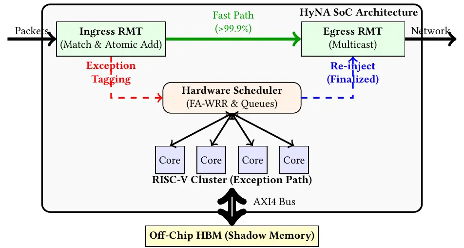
Anything else takes the exception path. The pipeline aborts the write and recirculates the packet with a 128-bit descriptor (cause, job ID, timestamp); a scheduler sends each block's packets to one core, to keep its caches warm. The core resolves a collision by cuckoo hashing: each key has several candidate slots, and an insert may move an older key to another one. These slots live in shadow memory, gigabytes of the switch's own packet-buffer memory (HBM in Broadcom Jericho3-AI, DRAM in Cisco Silicon One). Finished sums return by DMA into the egress pipeline (Figure 3).
其他情況都走例外路徑。管線中止寫入,帶著一個 128 位元的描述符(原因、任務 ID、時間戳)讓封包重新循環;排程器把同一區塊的封包都交給同一個核心,讓它的快取保持有效。核心以布穀鳥雜湊(cuckoo hashing)解決碰撞:每個鍵有幾個候選槽,插入時可能把舊的鍵移到另一個槽。這些槽位於影子記憶體,也就是交換器本身數 GB 的封包緩衝記憶體(Broadcom Jericho3-AI 的 HBM、Cisco Silicon One 的 DRAM)。完成的總和經 DMA 送回 egress 管線(圖 3)。
Why split? At about 1 ns per stage, RMT fits constrained cuckoo insertion (Caiazzi et al., CoNEXT 2023) but not rehashing plus FP32 adds. PsPIN and Flare run the reduction itself on cores; the paper argues that such symmetric designs pay for locks between cores.
為什麼分工?每個階段約 1 ns,RMT 放得下受限的布穀鳥插入(Caiazzi 等人,CoNEXT 2023),卻放不下重新雜湊再加上 FP32 加法。PsPIN 與 Flare 讓核心本身執行歸約;論文認為這類對稱式設計要付出核心之間加鎖的代價。
3.2 Speculative INT32, fail-safe FP323.2 先賭 INT32,再以 FP32 兜底
Switch ALUs add integers, so the workers quantize. Each block of 256 values gets one step size , sent in the header as a 16-bit exponent. (The paper calls the scale ; and the formula are our notation.)
交換器的 ALU 只會整數加法,所以由 worker 量化。每 256 個值 組成一個區塊,共用一個量化步長 ,以 16 位元的指數放在標頭中。(論文把尺度稱為 ; 與下式是我們的記號。)
This smallest fitting step keeps the most bits. (INT32 is as wide as FP32: quantizing buys integer adders, not fewer bytes.) But full-range values can sum past . Scaling for the sum would need an times coarser step and lose bits, 8 at (our arithmetic). HyNA keeps the bits and treats overflow as an exception. When steps differ, the switch uses the slot's coarsest step (the paper's "maximum ") and right-shifts the other integers.
這個放得下的最小步長保留最多位元。(INT32 和 FP32 一樣寬:量化換來的是整數加法器,不是更少的位元組。)但 個用滿範圍的值相加可能超過 。若為總和預留空間,步長要粗 倍,損失 個位元, 時是 8 個(我們的計算)。HyNA 保留這些位元,把溢位當成例外處理。步長不同時,交換器採用該槽最粗的步長(論文所說的「最大 」),把其他整數右移。
The first overflow in a slot triggers state promotion (Figure 4). In one clock cycle the pipeline reads the partial sum and resets the slot to a "zombie" state (an atomic destructive read). A core re-creates the slot in FP32 in shadow memory, and every later packet for it goes to the cores. Ownership moves once and one way, so hardware and software never share a block. The paper claims bit-level equivalence with an FP32 parameter server; saturating at instead diverged (section 5).
槽中的第一次溢位會觸發狀態升級(圖 4)。管線在一個時脈週期內讀出部分和,並把槽重設為「殭屍」狀態(一次原子的破壞性讀取)。核心在影子記憶體中以 FP32 重建這個槽,之後屬於它的每個封包都交給核心。所有權只移交一次、而且單向,所以硬體與軟體永遠不會共用一個區塊。論文宣稱結果與 FP32 參數伺服器逐位元等價;改成飽和在 則會發散(第 5 節)。
3.3 The switch asks for lost packets3.3 由交換器要求遺失的封包
HyNA runs over UDP, and the bitmap doubles as a loss detector. If a slot stays incomplete for 50 µs, the switch broadcasts a NACK with the bitmap, and the missing worker resends at once: a round trip of about 20 µs, against about 50 ms for a TCP or RoCE sender timeout (RTO). The bitmap also rejects duplicates.
HyNA 跑在 UDP 上,bitmap 同時用來偵測遺失。如果某個槽 50 µs 後仍未完成,交換器就廣播一個帶有 bitmap 的 NACK,缺少的 worker 立刻重送:往返約 20 µs,而 TCP 或 RoCE 的傳送端逾時(RTO)約 50 ms。bitmap 也擋掉重複的封包。
4. Implementation4. 實作
The prototype is a Xilinx Alveo U280 card, with its 8 GB of HBM2 as shadow memory. The fast path is P4 compiled to Verilog: a 512-bit bus at 250 MHz for 100 Gb/s, with UltraRAM as switch SRAM. The exception path is eight open-source RV64IMAF cores (CVA6) at 100 MHz, a pessimistic lower bound for ASIC cores above 1 GHz, the authors say. Resource use (the paper's Table 1; Alveo U280 FPGA prototype at 100 GbE):
原型是一張 Xilinx Alveo U280 卡,以卡上 8 GB 的 HBM2 作為影子記憶體。快速路徑以 P4 撰寫、編譯成 Verilog:512 位元的匯流排跑在 250 MHz,承載 100 Gb/s,並以 UltraRAM 充當交換器 SRAM。例外路徑是八個開源的 RV64IMAF 核心(CVA6),時脈 100 MHz;作者說它們是超過 1 GHz 的 ASIC 核心的悲觀下限。資源使用(論文的 Table 1;100 GbE 的 Alveo U280 FPGA 原型):
| Resource資源 | Used / available已用 / 可用 | Share比例 | Used for用途 |
|---|---|---|---|
| LUT | 234,510 / 1,303,680 | 17.98% | scheduler, core logic排程器、核心邏輯 |
| Flip-flops正反器 | 312,880 / 2,607,360 | 11.99% | pipelining, state管線化、狀態 |
| BRAM (36 Kb) | 980 / 2,016 | 48.61% | core L1 caches核心 L1 快取 |
| URAM (288 Kb) | 624 / 960 | 65.00% | aggregator slots聚合槽 |
| DSP | 1,080 / 9,024 | 11.96% | RISC-V FPUsRISC-V 浮點單元 |
(The paper puts the U280's URAM at about 90 Mb, but its Table 1 lists 960 URAMs of 288 Kb, about 270 Mb by our arithmetic; switch dies carry 256–512 Mb of SRAM.) For an ASIC, the authors synthesized one core in TSMC 7 nm and scaled up. These are synthesis estimates (the bus rows: the paper's analysis), not silicon:
(論文說 U280 只有約 90 Mb 的 URAM,但它的 Table 1 列出 960 個 288 Kb 的 URAM,依我們的計算約 270 Mb;交換器晶片則有 256–512 Mb 的 SRAM。)針對 ASIC,作者以 TSMC 7 nm 合成一個核心,再推估整體。這些是合成估計(匯流排兩列是論文的分析),不是實際晶片:
| Question問題 | Calculation算式 | Result結果 |
|---|---|---|
| Area: 32 cores, interconnect, RMT extensions (Table 2)面積:32 個核心、互連、RMT 擴充(Table 2) | mm² | |
| Share of a 12.8 Tb/s die of about 450 mm²占約 450 mm² 的 12.8 Tb/s 晶片 | the paper: 2.9%論文:2.9% | |
| Power: 9.4 W against about 250 W功耗:9.4 W 對約 250 W | its contribution list: 4.1%貢獻清單:4.1% | |
| Exception-bus demand at 12.8 Tb/s, 12.8 Tb/s、 時例外匯流排的需求 | Gb/sabout 8× below a 1.0 Tb/s bus約為 1.0 Tb/s 匯流排的 1/8 | |
| Exception rate that fills the bus填滿匯流排的例外比例 |
5. What was measured5. 量到了什麼
Setup. Except for convergence, every number here comes from the Alveo U280 FPGA prototype at 100 GbE; two servers replay traffic for up to 256 workers. A DPDK trace player runs up to 128 logical workers per port, each waiting for its sum before the next iteration, with traces from Llama-3 70B and DeepSeek-V2 236B (MoE, 90–95% gradient sparsity). In every comparison, ATP is re-implemented on HyNA's own FPGA, and BytePS's 11.5 Gb/s is a host CPU plus PCIe ceiling, not a limit of the parameter-server algorithm.
實驗設置。除收斂結果外,本節每個數字都來自 100 GbE 的 Alveo U280 FPGA 原型;由兩台伺服器重播最多 256 個 worker 的流量。DPDK 軌跡播放器在每個埠執行最多 128 個邏輯 worker,每個都要收到總和才進入下一個迭代,軌跡來自 Llama-3 70B 與 DeepSeek-V2 236B(MoE,梯度稀疏度 90–95%)。每項比較中,ATP 都是在 HyNA 自己的 FPGA 上重新實作的,而 BytePS 的 11.5 Gb/s 是主機 CPU 加 PCIe 的上限,不是參數伺服器演算法的上限。
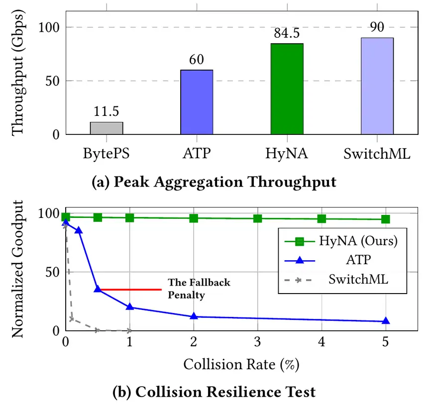
| Measurement量測項目 | HyNA | ATP | BytePS | SwitchML |
|---|---|---|---|---|
| Peak goodput, no collisions (Gb/s)無碰撞時的峰值有效吞吐(Gb/s) | 84.5 | 60 | 11.5 | 90 |
| Goodput as collisions rise碰撞增加時的有效吞吐 | at 5%5% 時 | down > 60% by 0.5%0.5% 時已降 60% 以上 | – | collapses at 0.1%0.1% 時崩潰 |
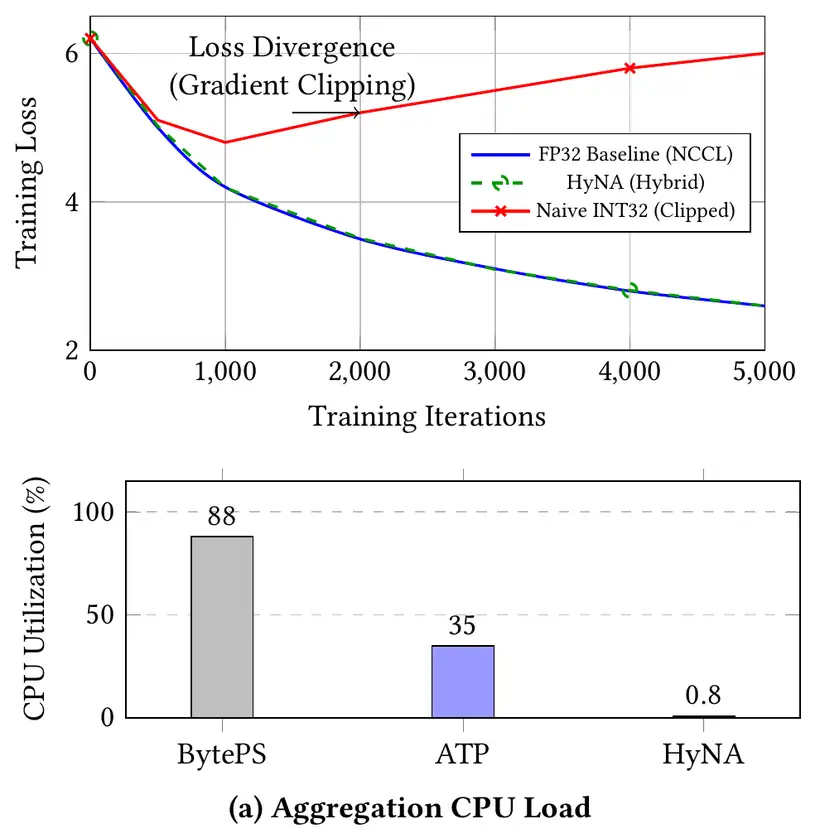
| Aggregation CPU on the servers伺服器上用於聚合的 CPU | 0.8% | up to 35%最高 35% | 88% | – |
HyNA reaches 7.35× BytePS and about 1.4× ATP, but 94% of SwitchML, which is fastest when nothing collides. The paper gives BytePS's CPU as 88% in the bar chart and as saturated at 100% in the text, and it does not say what the collision curves are normalized to.
HyNA 是 BytePS 的 7.35 倍、ATP 的約 1.4 倍,但只有 SwitchML 的 94%;沒有碰撞時 SwitchML 最快。論文的長條圖把 BytePS 的 CPU 寫成 88%,內文卻說它飽和到 100%;論文也沒有說明碰撞曲線以什麼為基準正規化。
With gradient traces replayed under the BSP barrier, HyNA's DeepSeek-V2 AllReduce phase ran 1.6× faster than ATP's and 2.3× faster than BytePS's. The end-to-end gain is the paper's estimate, assuming that AllReduce is 25% of an iteration:
以 BSP 屏障重播梯度軌跡時,HyNA 的 DeepSeek-V2 AllReduce 階段比 ATP 快 1.6 倍、比 BytePS 快 2.3 倍。端到端增益是論文的估計值,假設 AllReduce 占一次迭代的 25%:
| Question問題 | Calculation算式 | Result結果 |
|---|---|---|
| Iteration time saved by a 2.3× faster AllReduceAllReduce 快 2.3 倍可省下的迭代時間 | the paper calls it 14% more throughput; strictly 1.16×論文稱吞吐提高 14%;嚴格說是 1.16 倍 |
Convergence (training run; the paper does not say on what hardware). Llama-3 8B and Qwen 7B, trained from scratch on part of C4 for 5,000 iterations, ended within 0.05% validation accuracy of FP32 NCCL. With overflow redirection off and sums saturated ("Naive INT32"), the loss rose after about 1,000 iterations (Figure 6).
收斂(訓練執行;論文沒有說明使用什麼硬體)。Llama-3 8B 與 Qwen 7B 在部分 C4 資料上從頭訓練 5,000 個迭代,最終驗證準確率與 FP32 NCCL 相差不到 0.05%。關閉溢位轉送、把總和飽和(「Naive INT32」)時,loss 在約 1,000 個迭代後開始上升(圖 6)。
6. Limits and open questions6. 限制與未解的問題
The paper's own limits: only AllReduce is accelerated, which caps its estimate near 14%, and soft cores understate an ASIC. A careful reader adds:
論文自己的限制:只加速 AllReduce,使它的估計停在約 14%;軟核心低估了 ASIC。細心的讀者還會補上:
- One small switch: one 100 GbE FPGA, 256 emulated workers; no multi-switch tree, no 400–800 Gb/s, no switch failure.一台小交換器:一台 100 GbE 的 FPGA、256 個模擬的 worker;沒有多交換器的樹、沒有 400–800 Gb/s,也沒有交換器故障。
- Baselines: ATP is re-implemented on HyNA's FPGA, and BytePS's 11.5 Gb/s is a host CPU plus PCIe ceiling; NCCL and NVIDIA SHARP are not measured for speed.基準:ATP 是在 HyNA 的 FPGA 上重新實作的,BytePS 的 11.5 Gb/s 是主機 CPU 加 PCIe 的上限;NCCL 與 NVIDIA SHARP 都沒有量測速度。
- Which latency? "Under 200 ns" is the bus; a 100 MHz core's time to hash and add 360 FP32 values is not reported.哪一段延遲?「低於 200 ns」是匯流排;100 MHz 的核心雜湊並相加 360 個 FP32 值要多久,論文沒有報告。
- Which switch? Shadow memory needs a deep-buffer switch (Jericho3-AI, Silicon One class); the shallow single-chip switches common in AI fabrics (Chapter 2, section 04) have none.哪一種交換器?影子記憶體需要深緩衝交換器(Jericho3-AI、Silicon One 等級);AI 網路常見的淺緩衝單晶片交換器(第 2.5 節)沒有這種記憶體。
- Bit-identical? The evidence is accuracy within 0.05%; rounding to INT32 and the right-shifts can drop low-order bits before any overflow.逐位元相同?證據是準確率相差 0.05% 以內;量化成 INT32 的捨入與右移,在任何溢位之前就可能丟掉低位位元。
- Loose ends: besides the CPU and power figures above, the header figure has no scale field, and the monitor is sized for 1,024 workers while 256 were emulated.未解釋的出入:除了上面的 CPU 與功耗數字,標頭圖中沒有尺度欄位,而監控程式針對 1,024 個 worker 設計,實際只模擬了 256 個。
7. How it connects7. 與其他內容的關聯
- EPIC (the previous digest, same session) keeps RoCE NICs; HyNA uses UDP and switch NACKs. EPIC's Tofino path saturates on overflow, the rule that diverged in HyNA's ablation (with HyNA's tighter scaling, so not a test of EPIC). EPIC's NP switch, whose cores add every vector, stalled on shared SRAM, the cost that HyNA avoids by keeping cores off the common path.EPIC(上一篇導讀,同一場次)沿用 RoCE NIC;HyNA 用 UDP 與交換器 NACK。EPIC 的 Tofino 路徑在溢位時飽和,正是 HyNA 消融實驗中發散的規則(但 HyNA 的尺度更緊,所以這不是對 EPIC 的檢驗)。EPIC 的 NP 交換器由核心相加每個向量,卡在共用 SRAM 上;HyNA 讓核心離開常見路徑,正好避開這個代價。
- Chapter 4, section 9.5: HyNA reduces in the network but does not shrink bytes; ZipCCL and DynamiQ shrink them at the hosts.第 4 章第 9.5 節:HyNA 在網路中歸約,但不減少位元組;ZipCCL 與 DynamiQ 在主機端減少位元組。
- Chapter 10, section 6: the same maximum over ranks makes stragglers costly.第 10.6 節:同樣的「對所有 rank 取最大值」讓 straggler 代價高昂。
- Guided reading IRN: like selective retransmission, the bitmap NACK avoids long timeouts.論文導讀 IRN:和選擇性重傳一樣,bitmap NACK 避免了漫長的逾時。
Key numbers關鍵數字
| Number | 數字 | Meaning | 意義 |
|---|---|---|---|
| Alveo U280 FPGA prototype at 100 GbE; two servers replay traffic for up to 256 workers (ATP re-implemented on this FPGA; BytePS limited by host CPU plus PCIe)100 GbE 的 Alveo U280 FPGA 原型;兩台伺服器重播最多 256 個 worker 的流量(ATP 在此 FPGA 上重新實作;BytePS 受限於主機 CPU 加 PCIe) | |||
| 84.5 Gb/s | Peak goodput, no collisions (ATP 60, BytePS 11.5, SwitchML 90) | 無碰撞時的峰值有效吞吐(ATP 60、BytePS 11.5、SwitchML 90) | |
| Goodput kept at a 5% collision rate | 碰撞率 5% 時保有的有效吞吐 | ||
| 0.8% · 35% · 88% | Aggregation CPU: HyNA · ATP · BytePS | 用於聚合的 CPU:HyNA · ATP · BytePS | |
| 1.6× · 2.3× | DeepSeek-V2 AllReduce phase, vs ATP · BytePS | DeepSeek-V2 的 AllReduce 階段,對 ATP · BytePS | |
| Other sources其他來源 | |||
| Accuracy gap to FP32 NCCL (training run, hardware not stated) | 與 FP32 NCCL 的準確率差距(訓練執行,未說明硬體) | ||
| 0.08% · 1.8% | Exception rate, mean · p99 (DeepSeek-V2 traces) | 例外比例,平均 · p99(DeepSeek-V2 軌跡) | |
| 13.3 mm² · 9.4 W | Cores, interconnect, RMT extensions (7 nm synthesis estimate) | 核心、互連、RMT 擴充(7 nm 合成估計) | |
Terms used on this page本頁用到的術語
- In-network aggregation網內聚合
- Switches add the gradients, so each worker sends its data once and receives the sum once.
- 由交換器相加梯度,讓每個 worker 只送一次資料、收一次總和。
- RMT
- A switch's match-action pipeline: about 1 ns per stage, simple integer ALUs.
- 交換器的 match-action 管線:每階段約 1 ns,只有簡單的整數 ALU。
- Shadow memory影子記憶體
- The switch's packet-buffer memory, where the cores keep FP32 slots.
- 交換器的封包緩衝記憶體,核心在其中保存 FP32 槽。
- State promotion狀態升級
- A slot's one-way move from INT32 SRAM to FP32 shadow memory at its first overflow.
- 槽在第一次溢位時,從 INT32 SRAM 單向移到 FP32 影子記憶體。