The hardware: GPU, server, network card, switch and cable硬體:GPU、伺服器、網路卡、交換器與線纜
Learn the physical parts of a training cluster, the speed of each connection between them, and two rules (the roofline and the bandwidth-delay product) that tell you which connection limits a piece of work.認識訓練叢集的實體元件、元件之間每種連接的速度,以及兩條規則(roofline 與頻寬延遲乘積),用來判斷哪一種連接限制了一項工作。
This chapter builds on Chapters 1. These earlier terms appear most often below; each chip links to its definition.
本章建立在第 1 章之上。下列較早定義的名詞在本章最常出現;點選即可回到它的定義。
New terms in this chapter (33)本章新名詞(33)
Each term is defined in the text where it first appears; the link jumps there. Terms from earlier chapters are listed under "Before you start".
每個名詞都在它第一次出現的段落中定義,點連結可跳過去。前面各章的名詞列在「開始之前」。
- Server (host, node)伺服器(主機、節點) One computer in the cluster. A training server holds 8 GPUs, 2 CPUs and 8–9 network cards. 叢集中的一台電腦。訓練伺服器有 8 顆 GPU、2 顆 CPU 與 8–9 張網路卡。
- HBMHBM High-bandwidth memory: the GPU's own memory, stacked beside the chip; about 80 GB at 3.35 TB/s on an H100. 高頻寬記憶體:疊在 GPU 晶片旁的專屬記憶體;H100 約 80 GB、3.35 TB/s。
- NICNIC(網路卡) Network interface card: the device that sends and receives a server's network traffic; 400 Gb/s per GPU in current clusters. 網路介面卡:負責伺服器網路收發的裝置;現行叢集每顆 GPU 配 400 Gb/s。
- Packet, MTU封包、MTU A packet is one unit of data on the wire. The MTU is the largest payload one packet may carry (4 KB for RDMA). 封包是線路上的一個資料單位。MTU 是一個封包能攜帶的最大資料量(RDMA 為 4 KB)。
- Link鏈路(link) One cable between two ports, with its rate in each direction, such as 400 Gb/s. 兩個埠之間的一條線纜,具有各方向的速率,例如 400 Gb/s。
- Switch, port交換器、埠 A switch forwards packets between its ports; a port is one socket for one link. 交換器在各埠之間轉送封包;埠是接一條鏈路的插口。
- NVLink, NVSwitchNVLink、NVSwitch NVIDIA's GPU-to-GPU links inside a server, and the switch chips that join them; about 450 GB/s per GPU each way on H100. NVIDIA 在伺服器內連接 GPU 的鏈路,以及把它們接在一起的交換晶片;H100 每顆 GPU 每個方向約 450 GB/s。
- High-bandwidth domain (HBD)高頻寬域(HBD) The set of GPUs joined by NVLink: one 8-GPU server, or a whole rack in systems such as NVL72. 以 NVLink 相連的一組 GPU:一台 8-GPU 伺服器,或 NVL72 這類系統中的整個機櫃。
- Scale-up, scale-outScale-up、scale-out Scale-up is the fast fabric inside a high-bandwidth domain (NVLink); scale-out is the network between servers. Scale-up 指高頻寬域內的快速互連(NVLink);scale-out 指伺服器之間的網路。
- PCIePCIe The bus that connects GPUs and network cards to the CPUs inside a server; about 64 GB/s each way for Gen5 x16. 伺服器內連接 GPU、網路卡與 CPU 的匯流排;Gen5 x16 每個方向約 64 GB/s。
- RDMARDMA Remote direct memory access: the NIC reads and writes memory on another server without copies through the CPU. 遠端直接記憶體存取:NIC 直接讀寫另一台伺服器的記憶體,不經 CPU 複製。
- GPUDirect RDMAGPUDirect RDMA RDMA straight into GPU memory: the NIC moves data to and from HBM over PCIe with no copy in host memory. 直接進出 GPU 記憶體的 RDMA:NIC 經 PCIe 讀寫 HBM,不經主機記憶體複製。
- Roofline, arithmetic intensityRoofline、算術強度 Time ≥ max(operations ÷ peak rate, bytes ÷ bandwidth). Intensity is operations per byte; the balance point is where the two terms tie. 時間 ≥ max(運算量 ÷ 峰值速率, 位元組 ÷ 頻寬)。強度是每位元組的運算量;兩項相等處是平衡點。
- Flow流(flow) A stream of packets between two endpoints over one connection; in training, often one queue pair. 兩個端點之間經一條連線傳送的一串封包;訓練中常對應一個佇列對。
- Ethernet, InfiniBandEthernet、InfiniBand The two network families used for training: Ethernet, the data-center standard, and InfiniBand, built for RDMA. 訓練所用的兩大網路家族:資料中心標準 Ethernet,與為 RDMA 而設計的 InfiniBand。
- Queue pair (QP)佇列對(QP) One RDMA connection: a send queue and a receive queue whose state the NIC keeps. 一條 RDMA 連線:一個送出佇列加一個接收佇列,狀態存在 NIC 內。
- DPUDPU Data processing unit: a NIC with its own processor cores for storage, networking and virtualization work. 資料處理單元:帶有自身處理器核心的 NIC,用於儲存、網路與虛擬化工作。
- Radix基數(radix) The number of ports on one switch chip at a given speed: 128 × 400G for a 51.2 Tb/s chip. 一顆交換晶片在某速率下的埠數:51.2 Tb/s 晶片為 128 × 400G。
- SerDes laneSerDes 通道 One high-speed serial signal; a port is 4 or 8 lanes, and a chip's capacity is lanes × lane rate. 一路高速串列訊號;一個埠由 4 或 8 個通道組成,晶片容量是通道數 × 通道速率。
- Breakout分接(breakout) Splitting one fast port into several slower links, such as one 400G port into two 200G links. 把一個高速埠拆成多條較慢的鏈路,例如一個 400G 埠拆成兩條 200G。
- Uplink, downlink上行、下行 A switch's ports toward the tier above (uplinks) and toward hosts or the tier below (downlinks). 交換器朝上一層的埠(上行)與朝主機或下一層的埠(下行)。
- Oversubscription超額認購 Bandwidth entering a tier from below divided by bandwidth leaving upward; 1:1 is non-blocking. 從下方進入一層的頻寬除以向上離開的頻寬;1:1 為非阻塞。
- Transceiver, optics光模組 The plug-in module that turns a port's electrical signal into light and back; about 9 W and $199 in one paper's model. 把埠的電訊號轉成光、再轉回來的可插拔模組;某論文模型中約 9 W、199 美元。
- DAC, AOC, multi-mode, single-modeDAC、AOC、多模、單模 Cable types by reach: copper (about 3 m), active optical cable and multi-mode fiber (about 100 m), single-mode fiber (500 m and more). 依距離分的線纜:銅線(約 3 m)、主動光纜與多模光纖(約 100 m)、單模光纖(500 m 以上)。
- Link flap鏈路抖動(link flap) A link that goes down and comes back within seconds, usually from marginal optics. 在數秒內斷線又恢復的鏈路,通常因光學元件品質不佳。
- Latency延遲 The time before the first byte arrives, as opposed to how fast bytes flow once they start. 第一個位元組抵達前的時間,相對於開始後位元組流動的速度。
- Hop跳(hop) One switch that a packet crosses on its way. 封包途中經過的一台交換器。
- Round-trip time (RTT)往返時間(RTT) The time for a packet to reach the far end and for the answer to come back; about 22 µs in Meta's fabric. 封包抵達對端、回覆再傳回所需的時間;Meta 的網路約 22 µs。
- Bandwidth-delay product (BDP)頻寬延遲乘積(BDP) Link rate × round-trip time: the bytes a sender must have in flight to keep a link busy; 1.1 MB at 400 Gb/s and 22 µs. 鏈路速率 × 往返時間:要讓鏈路保持忙碌,傳送端必須在途的位元組數;400 Gb/s、22 µs 時為 1.1 MB。
- Bytes in flight在途位元組 Data sent but not yet acknowledged. A link stays busy only if bytes in flight ≥ the BDP. 已送出但尚未確認的資料。只有在途位元組 ≥ BDP,鏈路才會保持忙碌。
- Congestion, congestion control壅塞、壅塞控制 A link or port asked to carry more than its rate, so a queue grows; congestion control slows the senders. 鏈路或埠被要求承載超過其速率,佇列因而增長;壅塞控制會讓傳送端降速。
- Switch buffer (shallow, deep)交換器緩衝(淺、深) Memory in a switch that holds packets waiting for a busy port: tens of MB on one chip (shallow), gigabytes in a chassis (deep). 交換器內暫存等待忙碌埠之封包的記憶體:單晶片為數十 MB(淺),機框式為數 GB(深)。
- Go-back-N, selective retransmissionGo-back-N、選擇性重傳 Two ways to recover a lost packet: resend it and everything after it (go-back-N), or resend only the missing one (selective). 兩種遺失恢復方式:重送遺失封包及其後所有封包(go-back-N),或只重送缺的那一個(選擇性重傳)。
2.1Inside a training server訓練伺服器的內部
This chapter introduces the hardware that makes up a distributed training cluster and explains how communication bandwidth changes as data moves through it. A cluster consists of multiple servers, also called hosts or nodes, each containing several GPUs with their own high-bandwidth memory (HBM). Within a server, GPUs communicate through high-speed interconnects, while communication across servers relies on network interface cards (NICs), which transmit data in packets over physical links connected by switches. As data moves from GPU memory to intra-server connections and eventually to the inter-server network, the available bandwidth generally decreases, often by an order of magnitude between levels. This bandwidth hierarchy has important consequences for distributed training performance and motivates many of the system designs discussed in later chapters. Throughout the discussion, we draw on three production clusters to illustrate these tradeoffs, including Meta's Llama 3 cluster, Alibaba's High-Performance Network (HPN), and ByteDance's MegaScale.
本章介紹構成分散式訓練叢集的硬體,並說明資料在其中移動時,可用的通訊頻寬如何隨之改變。一個叢集由多台伺服器組成,伺服器也稱為主機或節點,每台伺服器內有數顆 GPU,而每顆 GPU 都配有自己的高頻寬記憶體(HBM)。同一台伺服器內的 GPU 透過高速互連彼此通訊,跨伺服器的通訊則仰賴網路介面卡(NIC),網路卡把資料切成封包,經由實體鏈路送出,而這些鏈路由交換器串接起來。當資料從 GPU 記憶體出發,先經過伺服器內的連接,最後進入伺服器之間的網路,可用頻寬通常一路下降,相鄰兩層之間往往相差一個數量級。這種頻寬階層對分散式訓練的效能有重大影響,也是後面各章許多系統設計的出發點。整個討論中,我們以三個生產叢集來說明這些取捨,分別是 Meta 的 Llama 3 叢集、阿里巴巴的高效能網路(HPN),以及字節跳動的 MegaScale。
A training server usually holds 8 GPUs. Inside the server, the GPUs connect through NVLink and NVSwitch chips. This is a short, very fast fabric, and it is non-blocking: every GPU can send to any other at full speed at the same time. On an H100 server, each GPU can move about 900 GB/s in and out over NVLink. The GPUs in one server form a high-bandwidth domain (HBD). Some newer systems extend this domain to 72 GPUs in one rack (NVIDIA GB200 NVL72).
一台訓練伺服器通常裝 8 顆 GPU。伺服器內部,GPU 之間透過 NVLink 與 NVSwitch 晶片連接。這是一個距離短、速度極快的互連,而且是非阻塞的:每顆 GPU 都能同時以全速送資料給任何另一顆。在 H100 伺服器上,每顆 GPU 經 NVLink 進出的頻寬約 900 GB/s。同一台伺服器內的 GPU 構成一個高頻寬域(HBD)。較新的系統把這個域擴大到一個機櫃 72 顆 GPU(NVIDIA GB200 NVL72)。
Each GPU also has its own NIC (network interface card) for traffic to other servers. A modern NIC runs at 400 Gb/s, which is 50 GB/s. Compare: NVLink gives about 450 GB/s in each direction, 9× the NIC. Many sources add NVLink's two directions together and quote 900 GB/s and 18× (Section 2.2 sorts this out). Either way, the connection inside the server is about ten times faster than the network. This is the first rule of AI network design: keep as much traffic as possible inside the server.
每顆 GPU 也有自己的 NIC(網路介面卡),用來與其他伺服器通訊。現代 NIC 的速率是 400 Gb/s,也就是 50 GB/s。比較一下:NVLink 每方向約 450 GB/s,是 NIC 的 9 倍。許多資料把 NVLink 兩個方向加總,寫成 900 GB/s 與 18 倍(第 2.2 節會釐清)。無論哪種算法,伺服器內的連接都比網路快約十倍。這是 AI 網路設計的第一條規則:盡可能把流量留在伺服器內部。
The industry uses two words. Scale-up is the fabric inside the high-bandwidth domain (NVLink). Scale-out is the network between servers, built from NICs, switches and links. This book is mostly about scale-out. But the size of the scale-up domain decides how much traffic reaches the scale-out network, so the two must be designed together.
業界用兩個詞。Scale-up 是高頻寬域內部的互連(NVLink)。Scale-out 是伺服器之間由 NIC、交換器與鏈路構成的網路。本書主要談 scale-out。但 scale-up 域的大小決定了有多少流量會落到 scale-out 網路上,所以兩者必須一起設計。
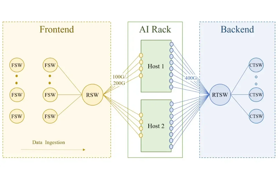
The three production clusters share a similar server architecture built around eight GPUs connected through a high-bandwidth intra-server fabric. In Meta's Grand Teton, NVSwitch connects the eight GPUs, while two CPUs and eight 400 Gb/s NICs provide a total of 3.2 Tb/s of bandwidth to the back-end network, the network that carries training traffic between GPUs in different servers (Meta's network paper; Llama 3 §3.3.1; Figure 2.1). Separate front-end interfaces handle storage and management traffic (Chapter 9). Alibaba's HPN follows a similar design but uses nine NICs, with one dedicated to the front end and the remaining eight each providing two 200 Gb/s connections to the back end, preserving the same aggregate bandwidth of 3.2 Tb/s (HPN §3). NVIDIA's DGX H100 reference design adopts a comparable configuration with eight GPUs, four NVSwitch chips, eight ConnectX-7 NICs, and two CPUs. Each H100 GPU provides 80 GB of HBM3 memory and has a rated power consumption of 700 W, as reported in the Llama 3 paper.
三個生產叢集的伺服器架構相近,都以八顆 GPU 為核心,並透過伺服器內的高頻寬互連把它們連在一起。在 Meta 的 Grand Teton 中,NVSwitch 連接八顆 GPU,兩顆 CPU 與八張 400 Gb/s 的 NIC 則為後端網路提供總共 3.2 Tb/s 的頻寬,後端網路就是在不同伺服器的 GPU 之間承載訓練流量的網路(Meta 的網路論文;Llama 3 §3.3.1;圖 2.1)。另外有獨立的前端介面負責儲存與管理流量(第 9 章)。阿里巴巴的 HPN 採用類似的設計,但使用九張 NIC,其中一張專門服務前端,其餘八張各以兩條 200 Gb/s 的連接接到後端,因此總頻寬同樣維持在 3.2 Tb/s(HPN §3)。NVIDIA 的 DGX H100 參考設計也採用相近的配置,包含八顆 GPU、四顆 NVSwitch 晶片、八張 ConnectX-7 NIC 與兩顆 CPU。根據 Llama 3 論文,每顆 H100 GPU 配有 80 GB 的 HBM3 記憶體,額定功率為 700 W。
The PCIe path and GPUDirect RDMAPCIe 路徑與 GPUDirect RDMA
Inside the server, the GPUs and NICs hang off a tree of PCIe (PCI Express) links, the standard connection between a computer's processors and its add-in cards. Each CPU has a root complex, from which PCIe switches fan out, and each GPU attaches to a PCIe switch with a Gen5 x16 link while its NIC attaches to the same switch. RDMA (remote direct memory access) lets a NIC read or write another machine's memory directly, without involving the CPU on either side. To send data, the CPU hands the NIC a short instruction called a work request (WR), which says where the data sits in memory, where it should go and how many bytes to send, and the NIC then fetches the data by itself. A work request can only point at memory that the NIC is able to read, and this is exactly where GPUDirect RDMA, which lets the NIC read and write GPU memory directly, makes the difference.
Take a gradient that has just been computed in a GPU's HBM and must be sent to other GPUs during synchronization. Without GPUDirect RDMA, the NIC can read only host memory, so the gradient is first copied from HBM into host DRAM, the CPU then tells the NIC to fetch it from that DRAM location and send it, and the NIC reads it out of DRAM onto the network. With GPUDirect RDMA, the GPU's HBM is made readable to the NIC over PCIe, so the CPU tells the NIC to fetch the gradient straight from its location in HBM, and the NIC reads it through the PCIe switch that it shares with the GPU. The only difference between the two paths is the copy into DRAM, which GPUDirect RDMA removes. Why this matters: in each direction, while a CPU socket's memory bus has a few hundred GB/s in total. Copying every byte through host memory would consume that bus twice over and add microseconds to every message. The data path for training traffic is NIC → PCIe switch → HBM and back (Figure 2.2), with the CPUs as controllers, not movers.
伺服器內部,GPU 與 NIC 掛在一棵由 PCIe(PCI Express,電腦處理器與擴充卡之間的標準連接)鏈路組成的樹上。每顆 CPU 有一個 root complex,PCIe 交換器從它向外展開,每顆 GPU 以一條 Gen5 x16 鏈路接到某個 PCIe 交換器,而這顆 GPU 的 NIC 也接在同一個交換器上。RDMA(remote direct memory access,遠端直接記憶體存取)讓 NIC 直接讀寫另一台機器的記憶體,兩端的 CPU 都不必參與。要送出資料時,CPU 交給 NIC 一則稱為工作請求(work request,WR)的簡短指令,說明資料放在記憶體的哪裡、要送到哪裡、送多少位元組,接著由 NIC 自己去把資料讀出來。工作請求只能指向 NIC 讀得到的記憶體,而讓 NIC 能直接讀寫 GPU 記憶體的 GPUDirect RDMA,差別正是在這裡。
以一份剛在 GPU 的 HBM 裡算好、要在同步時送給其他 GPU 的梯度為例。沒有 GPUDirect RDMA 時,NIC 只能讀主機記憶體,所以梯度要先從 HBM 複製到主機的 DRAM,CPU 再告訴 NIC 去 DRAM 的這個位置拿資料送給對方,NIC 才從 DRAM 讀出梯度送上網路。有了 GPUDirect RDMA,GPU 的 HBM 可以讓 NIC 透過 PCIe 直接讀取,所以 CPU 直接告訴 NIC 去 HBM 的這個位置拿資料,NIC 便經由它和 GPU 共用的 PCIe 交換器把梯度讀出來送上網路。兩條路徑唯一的差別,就是複製到 DRAM 的那一趟,而 GPUDirect RDMA 把它省掉了。這為什麼重要:每方向 ,而一個 CPU 插槽的記憶體匯流排總共只有幾百 GB/s。若每個位元組都經主機記憶體複製,會把那條匯流排用掉兩遍,還為每一則訊息增加數微秒。訓練流量的資料路徑是 NIC → PCIe 交換器 → HBM 再回來(圖 2.2),CPU 是控制者而不是搬運者。
Animation 2.1 plays the same send two ways: by GPUDirect RDMA, and by a copy through host memory.
動畫 2.1 用兩種方式播放同一次發送:GPUDirect RDMA,以及經主機記憶體複製。
Why one NIC per GPU. A 400G NIC needs 50 GB/s of host bandwidth in each direction. One PCIe Gen5 x16 slot gives about 64 GB/s raw, less after the protocol's own overhead, so one NIC nearly fills one slot. Each GPU therefore gets its own NIC on its own x16 link, and the eight NICs give the server 3.2 Tb/s. An 800 Gb/s NIC needs about 100 GB/s per direction, more than a Gen5 x16 slot can carry, which is why 800G NICs arrive together with PCIe Gen6 or a wider host attach, and why GPU and NIC generations move together.
為什麼每顆 GPU 一張 NIC。一張 400G NIC 每方向需要 50 GB/s 的主機頻寬。一個 PCIe Gen5 x16 插槽的原始頻寬約 64 GB/s,扣掉協定本身的額外負擔後更少,所以一張 NIC 幾乎填滿一個插槽。因此每顆 GPU 在自己的 x16 鏈路上有自己的 NIC,八張 NIC 給伺服器 3.2 Tb/s。一張 800 Gb/s 的 NIC 每方向需要約 100 GB/s,超過 Gen5 x16 插槽的承載量,這就是為什麼 800G NIC 會與 PCIe Gen6 或更寬的主機介面一起出現,也是 GPU 與 NIC 世代一起前進的原因。
Panel 2.1 pairs a PCIe generation with a NIC speed and shows when one slot is no longer enough.
面板 2.1 把 PCIe 世代與 NIC 速率配對,顯示一個插槽何時不再夠用。
Power per server, per rack, per building每台伺服器、每個機櫃、每棟建築的功耗
Eight H100 GPUs at 700 W each draw 5.6 kW. The two CPUs, four NVSwitch chips, nine NICs, two terabytes of DRAM, storage and fans add several kilowatts more, so a full server draws about 10 kW at load. A Meta rack holds two such servers under one Minipack2 switch (Llama 3 §3.3.1), which is about 20 kW of servers plus the switch. The HPN paper gives the building-level figure: each Alibaba Cloud data-center building is limited to 18 MW, which the authors equate to about 15,000 GPUs. Divide: per GPU, all in. That is 1.7× the GPU's own 700 W rating. The difference is the CPUs, NVSwitch, NICs, switches, optical modules, storage and cooling that every GPU brings with it.
八顆 700 W 的 H100 耗 5.6 kW。兩顆 CPU、四顆 NVSwitch 晶片、九張 NIC、兩 TB 的 DRAM、儲存與風扇再加上好幾 kW,所以一台滿載的伺服器約耗 10 kW。Meta 的一個機櫃在一台 Minipack2 交換器下放兩台這樣的伺服器(Llama 3 §3.3.1),約 20 kW 的伺服器再加上交換器。HPN 論文給出建築層級的數字:阿里雲每棟資料中心建築的上限是 18 MW,作者把它等同於約 15,000 顆 GPU。除一下:每顆 GPU ,全部算進去。那是 GPU 本身 700 W 額定值的 1.7 倍。差額就是每顆 GPU 帶來的 CPU、NVSwitch、NIC、交換器、光模組、儲存與冷卻。
2.2The bandwidth ladder頻寬階梯
A GPU moves data over four kinds of link. Each link is further from the die than the one before it. Each is also slower, by roughly a factor of ten. This is not an accident of one product generation. It follows from packaging and physics. Many short wires carry more bits than few long wires.
GPU 透過四種鏈路搬資料。每一種鏈路都比前一種離晶粒更遠,也都慢大約十倍。這不是某一個產品世代的偶然,而是封裝與物理的結果:許多條短導線能承載的位元,多於少數幾條長導線。
The bandwidth of any link is HBM (high-bandwidth memory) stacks sit a few millimetres from the GPU die on a silicon interposer. Each stack has a 1,024-bit bus. Thousands of slow wires add up to terabytes per second. NVLink runs across the board to NVSwitch chips over tens of differential pairs, each at about 50 Gb/s. An H100 has 18 links of 50 GB/s each, which is 900 GB/s counted in both directions. PCIe Gen5 x16 has 16 lanes at 32 GT/s, which is about 64 GB/s in each direction after encoding. The NIC port is 8 lanes of 50 Gb/s PAM4 signalling, which is 400 Gb/s or 50 GB/s in each direction. As the link gets longer, the lanes get fewer, and the bits must be serialized and coded. Bandwidth falls one decade per rung (Figure 2.3).
任何鏈路的頻寬都是 HBM(高頻寬記憶體)堆疊透過矽中介層坐在距 GPU 晶粒幾毫米的地方,每個堆疊有 1,024 位元寬的匯流排。數千條慢速導線加總起來就是每秒數 TB。NVLink 穿過主機板到 NVSwitch 晶片,走的是數十對差動訊號線,每對約 50 Gb/s。一顆 H100 有 18 條各 50 GB/s 的鏈路,雙向合計 900 GB/s。PCIe Gen5 x16 有 16 條 lane、每條 32 GT/s,扣除編碼後每方向約 64 GB/s。NIC 的埠是 8 條 50 Gb/s 的 PAM4 訊號 lane,合計 400 Gb/s,也就是每方向 50 GB/s。鏈路越長,lane 越少,位元還必須序列化與編碼。頻寬每下一階就掉一個數量級(圖 2.3)。
| Rung (per GPU) | 階(每 GPU) | A100 | H100 | B200 | Ratio to one 400G NIC (H100) | 相對一張 400G NIC(H100) |
|---|---|---|---|---|---|---|
| HBM bandwidth | HBM 頻寬 | about 2 TB/s | about 3.35 TB/s | about 8 TB/s | 67× | |
| NVLink, both directions | NVLink,雙向 | 600 GB/s | 900 GB/s | 1.8 TB/s | 18× | |
| NVLink, one direction (NVSwitch, non-blocking) | NVLink,單向(NVSwitch,非阻塞) | 300 GB/s | 450 GB/s = 3.6 Tb/s | 900 GB/s | 9× | |
| PCIe x16, one direction | PCIe x16,單向 | Gen4: about 32 GB/s | Gen5: about 64 GB/s | Gen5: about 64 GB/s | 1.3× | |
| NIC, one direction | NIC,單向 | 200G = 25 GB/s | 400G = 50 GB/s | 400G or 800G = 100 GB/s | 1× |
Two ways to count the same gap. The common 18× divides NVLink in both directions (900 GB/s) by the NIC in one direction (50 GB/s). The "about 9×" of the rail-only paper (a 2024 study by Wang and colleagues, named after the network design it proposes in Chapter 6) divides one direction by one direction, 450 GB/s against 50 GB/s; the same paper states the DGX H100 NVSwitch fabric as 3.6 Tb/s per GPU, which is that 450 GB/s. HPN quotes 4–9×, spanning generations and port speeds. None is wrong. When a paper gives a ratio, check which direction it counts before you compare.
同一個差距的兩種算法。常見的 18 倍是把雙向的 NVLink(900 GB/s)除以單向的 NIC(50 GB/s)。Rail-only 論文(Wang 等人 2024 年的研究,以它在第 6 章提出的網路設計命名)的「約 9 倍」是單向除以單向,450 GB/s 對 50 GB/s;同一篇論文把 DGX H100 的 NVSwitch 互連寫成每顆 GPU 3.6 Tb/s,正是那個 450 GB/s。HPN 引用 4–9 倍,橫跨不同世代與埠速。沒有一個是錯的。當論文給出一個比例時,比較之前先確認它算的是哪個方向。
Worked example: 1 GB on each rung算例:1 GB 走過每一階
Take 1 GB of data and move it over each rung of an H100 server with 400G NICs. Then suppose an exchange of that size had to happen in every one of the 126 layers of Llama 3 405B, as one of the ways of splitting a model in Chapter 3 requires:
取 1 GB 的資料,讓它走過配備 400G NIC 的 H100 伺服器的每一階。再假設這麼大的交換必須在 Llama 3 405B 的 126 層每一層都做一次,正如第 3 章的一種模型切分方式所要求的:
| Transfer傳輸 | Calculation算式 | Result結果 |
|---|---|---|
| 1 GB over HBM (3.35 TB/s)1 GB 走 HBM(3.35 TB/s) | ms | |
| 1 GB over NVLink, one direction (450 GB/s)1 GB 走單向 NVLink(450 GB/s) | ms | |
| 1 GB over PCIe Gen5 x16 (64 GB/s)1 GB 走 PCIe Gen5 x16(64 GB/s) | ms | |
| 1 GB over the NIC (400G, 50 GB/s)1 GB 走 NIC(400G,50 GB/s) | ms | |
| One such exchange in each of the 126 layers, on NVLink126 層各做一次這樣的交換,走 NVLink | sper pass每一趟 | |
| The same on the NIC同樣的量走 NIC | sper pass每一趟 |
Each pass through the model would spend 0.28 s in these exchanges on NVLink, but 2.5 s on the NIC. The GPU would spend more time waiting than computing. That difference is why the split that exchanges data inside every layer, tensor parallelism (Chapter 3), is kept inside one server. The panel below lets you redo this arithmetic for any generation, NIC speed and transfer size.
模型每跑一趟,這些交換在 NVLink 上花 0.28 秒,在 NIC 上卻要 2.5 秒。GPU 等待的時間會比計算的時間還長。這個差距就是每一層都要交換資料的切分方式——張量平行(第 3 章)——被留在同一台伺服器內的原因。下面的面板讓你對任何世代、NIC 速率與傳輸大小重做這個算術。
Set B200 and keep the NIC at 400G. The NVLink-to-NIC ratio becomes 36×. If the model and the way it is split do not change, what happens to the share of step time spent on the network, and which single hardware change restores the H100 balance? Check your answer with the 800G button.
選 B200,NIC 維持 400G。NVLink 對 NIC 的比例變成 36 倍。若模型與它的切分方式都不變,每步花在網路上的時間比例會怎樣?哪一個單一的硬體改動能恢復 H100 時的平衡?用 800G 按鈕檢查你的答案。
2.3Compute-bound or bandwidth-bound: the roofline計算受限還是頻寬受限:roofline
One rule tells you which rung limits a piece of work: the roofline. Any phase of a step needs a certain number of operations and a certain number of bytes moved. The time it takes is at least the larger of two ratios:
有一條規則能告訴你哪一階限制了一項工作:roofline(屋頂線)模型。一個步的任何階段都需要一定次數的運算與一定量的位元組搬動。它花的時間至少是下面兩個比值中較大的那個:
If the first term wins, the phase is compute-bound. If the second wins, it is bandwidth-bound. The ratio is the arithmetic intensity, and the ratio is the machine balance. For an H100 against its own memory, the balance is about FLOP per byte. A large matrix multiply has an intensity far above that, so the forward and backward passes are compute-bound. Now apply the same rule to the network. The balance of one GPU against its NIC, at the 400 TFLOP/s actually achieved, is about 8,000 FLOP per byte sent:
前者較大,這個階段就是計算受限。後者較大,就是頻寬受限。 叫算術強度, 叫機器平衡點。H100 對自己的記憶體,平衡點約為每位元組 次浮點運算。大型矩陣乘法的強度遠高於此,所以前向與反向是計算受限。現在把同一條規則用在網路上。一顆 GPU 對它的 NIC,以實際達到的 400 TFLOP/s 計,平衡點約為每送出一個位元組 8,000 次浮點運算:
A step whose arithmetic per GPU, divided by the bytes that GPU must send, falls below 8,000 is network-bound no matter how fast the GPU is. Chapter 5 computes both sides of that ratio for Llama 3 405B and draws the roofline for one step.
如果一個步在每顆 GPU 上的算術量除以該 GPU 必須送出的位元組低於 8,000,不論 GPU 多快,這一步都是網路受限。第 5 章會為 Llama 3 405B 算出這個比值的分子與分母,並畫出一步的 roofline。
2.4The network card and RDMA網路卡與 RDMA
Data crosses a network in packets: pieces of a message, each with a header that says where it goes and which piece it is. The largest packet a link accepts is its MTU (maximum transmission unit); 4 KB is common in training clusters. The packets that carry one stream of data between the same two endpoints form a flow; switches keep the packets of one flow on one path, so that they arrive in order (Chapter 8). Two network technologies carry training traffic: Ethernet, the standard of almost every data center, and InfiniBand, a network built for supercomputers. Meta, Alibaba and ByteDance all use Ethernet. Running RDMA (introduced in Section 2.1) over Ethernet is called RoCE, RDMA over Converged Ethernet (Chapter 7); Meta's 2024 paper on its training network, which this book cites as the Meta RoCE paper, is named after it.
資料以封包的形式穿越網路:每個封包是訊息的一小段,帶有一個標頭,說明它要去哪裡、是第幾段。一條鏈路接受的最大封包稱為 MTU(maximum transmission unit,最大傳輸單元);訓練叢集常用 4 KB。在相同兩端之間承載同一串資料的封包構成一條流(flow);交換器把同一條流的封包留在同一條路徑上,讓它們依序抵達(第 8 章)。承載訓練流量的網路技術有兩種:Ethernet(乙太網路),幾乎所有資料中心的標準;以及 InfiniBand,一種為超級電腦打造的網路。Meta、Alibaba 與 ByteDance 都用 Ethernet。在 Ethernet 上執行 RDMA(第 2.1 節)稱為 RoCE(RDMA over Converged Ethernet,第 7 章);Meta 2024 年關於其訓練網路的論文——本書稱為 Meta RoCE 論文——就以它命名。
An RDMA NIC does in hardware what TCP, the standard Internet transport, does in the operating-system kernel: it cuts messages into packets, numbers them, acknowledges them, retransmits losses, obeys flow control and limits its rate. A 2016 Microsoft paper on RDMA in its data centers gives the motivation: at 40 Gb/s, TCP at line rate already cost 6–12% of a 32-core server, while RDMA moved data between two machines' memories in a few microseconds with no CPU on the data path. At 400 Gb/s the kernel is not an option at all. Chapter 7 follows what the NIC does when packets are lost or delayed; this section covers the basics.
RDMA NIC 用硬體做 TCP(網際網路的標準傳輸協定)在作業系統核心裡做的事:把訊息切成封包、為它們編號、回覆確認、重傳遺失、遵守流量控制並限制速率。Microsoft 2016 年一篇關於其資料中心 RDMA 的論文給出動機:在 40 Gb/s,線速的 TCP 就已耗掉一台 32 核伺服器 6–12% 的 CPU,而 RDMA 在兩台機器的記憶體之間搬資料只需幾微秒,資料路徑上沒有 CPU。到了 400 Gb/s,核心根本不是選項。第 7 章會說明封包遺失或延遲時 NIC 怎麼做;本節只談基本概念。
A queue pair (QP) is one RDMA connection, and it consists of three queues that the application and the NIC share. The send queue holds the work requests that the application posts for the NIC to carry out in order, the completion queue is where the NIC reports each finished request, and the receive queue holds buffers that the application posts in advance for messages the other side sends with a two-sided SEND. An RDMA write needs only the sender's send queue and completion queue, because the data lands at the remote address that the sender names. The application posts a work request that names a local buffer, a remote address and a length. The NIC splits the message into packets of up to one MTU, adds a header that numbers them, and sends them. The receiving NIC writes the payload straight into the registered buffer and acknowledges (Figure 2.4). Every QP's state lives in NIC memory and a small on-chip cache. Training uses few QPs per GPU, a handful to a few dozen. Chapter 8 shows why some clusters deliberately open more QPs than they need, and what that costs the NIC.
Queue pair(QP)是一條 RDMA 連線,由應用程式與 NIC 共用的三個佇列組成。發送佇列存放應用程式提交、等待 NIC 依序執行的工作請求,完成佇列是 NIC 回報每個請求已完成的地方,接收佇列則存放應用程式預先放好的緩衝區,用來接收對方以雙邊 SEND 送來的訊息。RDMA 寫入只需要發送端的發送佇列與完成佇列,因為資料會直接落在發送端指定的遠端位址。應用程式提交一個工作請求,指明本地緩衝區、遠端位址與長度。NIC 把訊息切成最多一個 MTU 的封包,加上為它們編號的標頭後送出。接收端 NIC 把載荷直接寫進已註冊的緩衝區並回覆確認(圖 2.4)。每條 QP 的狀態放在 NIC 記憶體與一小塊晶片上的快取。訓練中每顆 GPU 用的 QP 很少,從幾條到幾十條。第 8 章會說明為什麼有些叢集刻意開比需要更多的 QP,以及這對 NIC 的代價。
The NIC in all three 2024 designs is a 400 Gb/s part of the ConnectX-7 class on a PCIe Gen5 x16 link, either as one 400G port (Meta, DGX H100) or as two 200G ports (HPN). The next generation is an 800 Gb/s class NIC with 100 Gb/s lanes; treat its details as "about" until a paper measures it. HPN's choice of two ports is a reliability decision: the two ports go to two different switches, so that one failed cable or switch slows a server down instead of cutting it off (Chapter 6 and Chapter 10). The front-end NIC is different again: HPN's front end carries storage, management and inference traffic at 2×200 Gb/s per host on a BlueField-3 class DPU, a NIC with its own processor cores for storage and virtualization work, so that none of it touches the eight back-end NICs.
三個 2024 年設計中的 NIC 都是 ConnectX-7 等級、接在 PCIe Gen5 x16 上的 400 Gb/s 元件,不是一個 400G 埠(Meta、DGX H100)就是兩個 200G 埠(HPN)。下一代是 lane 速率 100 Gb/s 的 800 Gb/s 等級 NIC;在有論文量測之前,把它的細節當作「約」。HPN 選擇兩個埠是為了可靠性:兩個埠接到兩台不同的交換器,所以一條線纜或一台交換器故障只會讓伺服器變慢,而不會把它斷開(第 6 章與第 10 章)。前端 NIC 又不一樣:HPN 的前端以每台主機 2×200 Gb/s 在 BlueField-3 等級的 DPU 上承載儲存、管理與推論流量——那是一張有自己處理器核心、負責儲存與虛擬化工作的 NIC——所以這些流量都不碰那八張後端 NIC。
2.5The switch交換器
A switch forwards packets between its network ports, and its main hardware specifications are its radix, the rate of each port and its total switching capacity. The radix is the number of independent ports that a switch provides. When the total capacity is fixed, a higher radix leaves less bandwidth for each port but lets the switch connect more devices directly. A switching chip with 51.2 Tb/s of capacity, for example, can provide 128 ports of 400 Gb/s or 64 ports of 800 Gb/s. A higher radix reduces the number of switches and switch layers that a large network needs, which lowers the cost of building it, although the exact effect depends on how the network is wired (Chapter 6).
交換器(switch)負責在不同網路埠之間轉送封包,其主要硬體規格包括基數(radix)、每埠速率,以及總交換容量。Radix 表示交換器能提供多少個獨立的網路埠。當總交換容量固定時,較高的 radix 意味著每埠可分配的頻寬較低,但能直接連接更多設備。例如,一顆容量為 51.2 Tb/s 的交換晶片,可以提供 128 個 400 Gb/s 埠,或 64 個 800 Gb/s 埠。較高的 radix 有助於減少大型網路所需的交換器數量與層數,進而降低建置成本,具體影響取決於網路拓樸(第 6 章)。
A fixed-configuration switch consists of a switching chip, the high-speed electrical lanes that connect the chip to the external ports, cages for optical modules, a CPU that runs the switch's control software, cooling and power supplies. The switching chip determines the total switching capacity of the device and the port rates it can support. Broadcom's Tomahawk family shows how these chips have evolved. Tomahawk 3 provides 12.8 Tb/s and supports 32 ports of 400G, Tomahawk 4 raises this to 25.6 Tb/s with 64 ports of 400G and is used in MegaScale, and Tomahawk 5, released in 2023, offers 51.2 Tb/s with 128 ports of 400G or 64 ports of 800G and is the hardware basis of Alibaba's HPN. HPN names 102.4 Tb/s switching chips as its next upgrade.
一台固定式交換器(fixed-configuration switch)主要由交換晶片、連接外部埠的高速電氣通道、光模組插槽、控制平面 CPU、散熱系統與電源組成。其中,交換晶片決定設備的總交換容量與可支援的埠速率。Broadcom 的 Tomahawk 系列展示了交換晶片的演進。Tomahawk 3 提供 12.8 Tb/s,支援 32 個 400G 埠;Tomahawk 4 提升至 25.6 Tb/s,支援 64 個 400G 埠,並被 MegaScale 採用;Tomahawk 5 則在 2023 年推出 51.2 Tb/s 的容量,支援 128 個 400G 埠或 64 個 800G 埠,也是 Alibaba HPN 的硬體基礎。HPN 進一步將 102.4 Tb/s 的交換晶片列為後續升級方向。
The switching chip exchanges data with external devices through SerDes (serializer/deserializer) circuits, which convert the parallel data inside the chip into high-speed serial signals, and each independent serial link is called a lane. The total capacity of a switching chip is the number of lanes multiplied by the rate of each lane, so the 512 SerDes lanes of 100 Gb/s in Tomahawk 5 provide 51.2 Tb/s in total. These lanes can be grouped into ports of different rates as needed, with 8 lanes forming an 800G port, 4 lanes a 400G port and 2 lanes a 200G port. The same chip can therefore trade the number of ports against the bandwidth of each port while its total capacity stays the same.
交換晶片透過 SerDes(Serializer/Deserializer)與外部設備傳輸資料。SerDes 將晶片內部的平行資料轉換為高速序列訊號,每條獨立通道稱為一條 lane。交換晶片的總容量可由 lane 數量乘上每條 lane 的傳輸速率計算。以 Tomahawk 5 為例,其 512 條 100 Gb/s SerDes lanes 提供總計 51.2 Tb/s 的容量。這些 lanes 可以依照需要組合成不同速率的埠,例如 8 條組成 800G 埠、4 條組成 400G 埠,或 2 條組成 200G 埠。因此,同一顆晶片能在埠數與每埠頻寬之間進行配置,而總交換容量維持不變。
Port breakout埠拆分
Port breakout lets a switch divide one high-speed port into several slower ports that operate independently. A 400G port, for example, can be split into two 200G ports, each connected to the NIC of a different host. On Tomahawk 5 this means dividing the 4 lanes of 100G that form a 400G port into two groups of 2 lanes, and a breakout cable or an optical module that supports breakout carries the two groups to different endpoints (Figure 2.5). After breakout the number of ports doubles and the rate of each port halves, while the total capacity of the switching chip stays the same.
埠拆分(port breakout)允許交換器將一個高速埠分成多個較低速、可獨立運作的埠。例如,一個 400G 埠可以拆成兩個 200G 埠,分別連接不同主機的 NIC。對 Tomahawk 5 而言,這相當於將原本組成 400G 埠的 4 條 100G SerDes lanes 分成兩組,每組 2 條。拆分線纜或支援 breakout 的光模組將這兩組訊號引導至不同的連接端點(圖 2.5)。拆分後的埠數加倍,每埠速率減半,交換晶片的總容量則維持不變。
HPN and MegaScale both use port breakout to match the 200G links of their servers' NICs. HPN uses the 51.2 Tb/s Tomahawk 5 and assigns 68 of its 128 400G-equivalent ports to downlinks, the ports that face the servers, splitting all of them into 136 ports of 200G, of which 128 are in normal use and 8 are held in reserve. The remaining 60 ports of 400G serve as uplinks to the switches in the layer above (Figure 2.6). In normal operation HPN therefore has 25.6 Tb/s of downlink capacity and 24 Tb/s of uplink capacity, an oversubscription ratio (downlink bandwidth divided by uplink bandwidth) of about 1.067:1, which follows from the port counts in §5.1 and Figure 7 of the HPN paper (Qian et al., SIGCOMM 2024). MegaScale likewise splits the 400G ports of Tomahawk 4 into 200G links to its servers' NICs (Chapter 6).
HPN 與 MegaScale 都利用埠拆分來配合伺服器 NIC 的 200G 連接速率。HPN 採用 51.2 Tb/s 的 Tomahawk 5,將其 128 個 400G 等效埠中的 68 個配置為連接伺服器的 downlink,並全部拆分為 136 個 200G 埠,其中 128 個正常使用,另外 8 個保留備用。其餘 60 個 400G 埠則作為連接上層交換器的 uplink(圖 2.6)。因此,HPN 的正常運作下行容量為 25.6 Tb/s,上行容量為 24 Tb/s,形成約 1.067:1 的頻寬超額配置比(oversubscription ratio,下行頻寬除以上行頻寬),這個比值由 HPN 論文(Qian 等人,SIGCOMM 2024)§5.1 與 Figure 7 列出的埠數算出。MegaScale 也採用類似方式,將 Tomahawk 4 的 400G 埠拆分為 200G 鏈路,以連接伺服器 NIC(第 6 章)。
Port breakout increases the number of NICs that one switch can connect, so a network can use the full capacity of a fast switching chip while still serving slower server interfaces. More endpoints, however, also add cables, optical module connectors and complexity to the physical wiring. In its early deployments HPN met a large number of wiring errors, which it identified and corrected only by sending probe packets through the network to verify the actual connections (Chapter 9).
埠拆分提高了單台交換器可連接的 NIC 數量,使網路能充分利用高速交換晶片的總容量,同時支援較低速的伺服器介面。然而,更多的連接端點也增加了線纜、光模組接頭與實體布線的複雜度。HPN 在早期部署時曾遇到大量接線錯誤,後來透過網路探測封包驗證實際連線關係,才得以辨識並修正這些問題(第 9 章)。
2.6Links, cables and optics鏈路、線纜與光學元件
A link is two switch or NIC ports, a medium between them, and, for optical links, a transceiver in each port. The transceiver takes the port's 8 electrical lanes, drives lasers or modulators, and recovers the signal at the far end with photodiodes. The 400G and 800G parts, often simply called optics, come in QSFP-DD or OSFP packages, draw about 9 W each (rail-only paper), and cost about $199 each in the same paper's model. Over a few meters, inside one rack, a link can be a plain copper cable, a DAC (direct-attach copper), with no transceiver at all. Beyond that, which transceiver you can use is decided by distance, and the distance is decided by how the building is laid out.
一條鏈路是兩個交換器或 NIC 的埠、它們之間的介質,以及(對光鏈路而言)每個埠裡的一個光模組。光模組接收埠的 8 條電氣 lane,驅動雷射或調變器,在遠端以光電二極體還原訊號。400G 與 800G 的模組(常簡稱 optics)採 QSFP-DD 或 OSFP 封裝,每個約耗 9 W(rail-only 論文),在同一篇論文的模型中每個約 199 美元。在幾公尺之內、同一個機櫃裡,鏈路可以是一條普通的銅纜,即 DAC(direct-attach copper,直連銅纜),完全不需要光模組。超過這個距離,能用哪一種光模組由距離決定,而距離由建築如何佈置決定。
| Medium | 介質 | Reach | 距離 | Transceivers | 光模組 | Where the papers use it | 論文中用在哪裡 |
|---|---|---|---|---|---|---|---|
| DAC, passive copper | DAC,被動式銅纜 | about 3 m at 400G, about 2 m at 800G | None; about 0 W | 無;約 0 W | Meta, from the rack's switch to the GPUs ("short copper cables") | Meta 機櫃交換器到 GPU(「短銅纜」) | |
| AOC, active optical cable | AOC,主動式光纜 | up to about 100 m | Fixed at both ends, multi-mode class | 兩端固定,多模等級 | MegaScale host links (NIC–AOC–switch signal quality) | MegaScale 的主機鏈路(NIC–AOC–交換器訊號品質) | |
| SR, multi-mode fiber (OM4) | SR,多模光纖(OM4) | about 100 m | Pluggable, about 70% cheaper than single-mode | 可插拔,比單模便宜約 70% | HPN: the whole GPU network fits in one building | HPN:整個 GPU 網路在一棟樓內 | |
| DR, single-mode fiber | DR,單模光纖 | about 500 m | Pluggable, the cost baseline (about $199 per module in the rail-only paper's model) | 可插拔,成本基準(rail-only 論文的模型中每個約 199 美元) | Meta, between rack switches and the larger switches above them (400G) | Meta,機櫃交換器與其上方較大交換器之間(400G) | |
| FR / LR, single-mode fiber | FR / LR,單模光纖 | about 2 km / 10 km | Pluggable, at or above the cost of DR | 可插拔,與 DR 相當或更高 | Between buildings; not needed inside one building | 建築之間;同一棟樓內不需要 |
Why distance sets the price為什麼距離決定價格
Multi-mode fiber has a wide core, so it accepts light from a cheap VCSEL laser and tolerates loose alignment, but the many paths through the core spread a pulse out, which limits the reach to about 100 m at 100 Gb/s per lane. Single-mode fiber has a narrow core that carries one path, so a pulse stays sharp for kilometers, but it needs precisely aligned, temperature-controlled lasers. That is where the 70% comes from. HPN's GPU network fits in one 18 MW building, so every fiber is under 100 m and every transceiver can be multi-mode (HPN §10; Figure 2.7). Meta's larger switches serve many racks and connect onward across the building, so Meta runs single-mode between rack switches and the switches above them, and keeps copper, with no transceivers at all, from the rack switch to the GPUs.
多模光纖的纖芯很寬,所以能接受便宜的 VCSEL 雷射的光、容許較鬆的對準,但纖芯內的多條路徑會把脈衝拉散,在每 lane 100 Gb/s 下距離限制在約 100 m。單模光纖的纖芯很窄、只承載一條路徑,所以脈衝能保持清晰數公里,但需要精準對準、溫度受控的雷射。70% 就是從這裡來的。HPN 的 GPU 網路放得進一棟 18 MW 建築,所以每條光纖都短於 100 m、每個光模組都可以是多模(HPN §10;圖 2.7)。Meta 較大的交換器服務許多機櫃,並跨越整棟建築往外連,所以 Meta 在機櫃交換器與其上方的交換器之間用單模,而從機櫃交換器到 GPU 用銅纜,完全不需要光模組。
Link failures and reliability鏈路故障與可靠性
High-speed network links are a common source of failures in large GPU training clusters. Aging optical modules, contaminated fiber connectors and poor signal quality between NICs, cables and switches can all cause transmission errors, and as SerDes rates rise to 100 Gb/s per lane, PAM4 signals become more sensitive to noise and signal loss. When signal quality degrades until the connection can no longer be held, the link may drop briefly and then recover, a behaviour called link flapping. Synchronous LLM training depends on every GPU finishing each exchange of data with the others, so even an outage of a few seconds can lose packets, trigger communication timeouts and stop the entire training job.
高速網路鏈路是大型 GPU 訓練叢集中常見的故障來源。光模組老化、光纖接頭污染,以及 NIC、線纜或交換器之間的訊號品質問題,都可能導致傳輸錯誤。隨著 SerDes 速率提升至每條 lane 100 Gb/s,PAM4 訊號對雜訊與訊號衰減更加敏感。當訊號品質惡化到無法維持連線時,鏈路可能短暫中斷後又恢復,這種現象稱為 link flapping。對需要同步執行 collective communication 的 LLM 訓練而言,即使只有幾秒鐘的中斷,也可能造成封包遺失、通訊逾時,甚至使整個訓練工作停止。
Failures of this kind are frequent in large clusters. Alibaba's HPN reports that about 0.057% of the links between NICs and their switches fail each month, and that its production fleet sees between 5,000 and 60,000 link flaps every day (HPN §2.3). At the same failure rate, a cluster with 100,000 links would lose about 57 of them in an average month. MegaScale also observed link flapping that stalled or slowed training, and traced the problem to signal quality between NICs, active optical cables (AOC) and switch ports. Its remedies were tighter control of hardware signal quality and a longer timeout in the communication library, which gives a briefly broken link the chance to recover before the training job fails (MegaScale §6.3).
這類故障在大型叢集中相當頻繁。Alibaba 的 HPN 報告指出,每個月約有 0.057% 的 NIC-to-ToR 鏈路發生故障,而整個生產環境每天會出現 5,000 至 60,000 次 link flap(HPN §2.3)。以 100,000 條鏈路的叢集為例,若故障率相同,平均每月約有 57 條鏈路發生故障。MegaScale 也觀察到 link flapping 導致訓練停滯或速度下降,並將問題追溯至 NIC、主動式光纖線纜(Active Optical Cable, AOC)及交換器埠之間的訊號品質。其改善方法包括加強硬體訊號品質管控,以及延長 NCCL 的通訊逾時設定,使短暫斷線後的鏈路有機會恢復,而不會立即導致訓練失敗(MegaScale §6.3)。
Some failures affect only one direction of a link. HPN met a case in which the optical signal from a NIC to its switch was faulty while the direction from the switch to the NIC still worked. The switch reported the fault to the NIC through Link Fault Signaling (LFS), but a bug in the NIC firmware kept the notification from being handled, so the NIC went on sending data over the faulty link and lost a large number of packets. Because HPN connects each NIC to two independent switches through its two 200G ports, this failure slowed training down without crashing the whole job (Chapter 10). Meta's Llama 3 training shows the same exposure to network faults. Of the 419 unexpected interruptions recorded over 54 days, 35 were attributed to switches or cables and another 7 to NICs, together about 10% of all interruptions (Llama 3 §3.3.4).
部分故障還可能只影響鏈路的單一傳輸方向。HPN 曾遇到 NIC 傳往 ToR 的光訊號異常,但 ToR 傳往 NIC 的方向仍正常的情況。交換器透過 Link Fault Signaling(LFS)通知 NIC 發生故障,然而 NIC 的韌體錯誤導致通知未被正確處理,使 NIC 持續透過異常鏈路傳送資料,造成大量封包遺失。HPN 採用的 dual-ToR 架構讓每張 NIC 透過兩個 200G 埠連接兩台獨立交換器,因此這次故障造成訓練效能下降,卻沒有使整個訓練工作崩潰(第 10 章)。Meta 的 Llama 3 訓練也反映了網路故障的影響。在 54 天內記錄的 419 次非預期訓練中斷中,35 次歸因於交換器或線纜,另有 7 次歸因於 NIC,合計約占全部中斷的 10%(Llama 3 §3.3.4)。
Switch power and cooling交換器的功耗與散熱
Power and cooling set another hardware limit on switches. As switching chips grew from 25.6 Tb/s to 51.2 Tb/s, the power of the chip that HPN uses rose by 45%, while the chip's maximum junction temperature stayed at 105 °C. HPN found that neither conventional heat pipes nor the vapor-chamber heat sink supplied by the switch vendor could keep the chip at a safe temperature under full load, and once the temperature limit is exceeded the chip triggers its overheating protection and stops forwarding data. The problem was mainly that heat from the center of the chip could not be carried away, so HPN redesigned the wick structure inside the vapor chamber and added heat-conducting pillars over the center of the chip, which raised the cooling capacity by 15% and let the switch run stably under heavy load (HPN §5.1).
交換器的另一項硬體限制來自功耗與散熱。隨著交換晶片容量從 25.6 Tb/s 提升至 51.2 Tb/s,HPN 所採用晶片的功耗增加了 45%,但晶片允許的最高接面溫度(maximum junction temperature)仍維持在 105°C。HPN 發現,傳統熱導管與交換器廠商提供的均熱板(vapor chamber)散熱器,都無法在晶片滿載時維持安全溫度。一旦超過溫度上限,晶片便會觸發過熱保護並停止資料傳輸。問題主要來自晶片中央的熱量無法有效散出,因此 HPN 重新設計均熱板內部的毛細結構,增加晶片中央區域的導熱支柱,使散熱能力提升 15%,讓交換器能在高負載下穩定運作(HPN §5.1)。
Besides the switching chip, the optical transceivers are a major consumer of power in a switch. The cost model of the rail-only paper assumes that each optical module costs $199 and draws 9 W, so a switch fitted with 128 optical modules needs about 1.15 kW for the modules alone, before the power of the switching chip, the fans and the other electronics is added. These numbers show that the total power of a switch depends on its optical interfaces as much as on its switching chip, while the actual values depend on how the device is configured and which optical modules it uses (rail-only §V-E).
除了交換晶片,光收發模組(optical transceiver)也是交換器的重要耗電來源。Rail-only 論文的成本模型假設每個光模組價格為 199 美元、功耗為 9 W。依此估算,一台配備 128 個光模組的交換器,光模組本身就需要約 1.15 kW,還須加上交換晶片、風扇及其他電子元件的功耗。這些數字說明了交換器整體功耗同時受到交換晶片與光學介面的影響,而實際數值仍取決於設備配置與使用的光模組(Rail-only §V-E)。
The industry has proposed two technical directions to lower the power of high-speed optical interfaces. Linear-drive Pluggable Optics (LPO) keep the pluggable module but remove the digital signal processor (DSP) that recovers the signal inside it, which lowers the module's power and places higher demands on the signal quality of the switching chip's SerDes. Co-Packaged Optics (CPO) instead place the optical engine next to the switching chip, shortening the distance that high-speed electrical signals travel from the chip to the optical engine and so reducing both signal loss and the power spent on electrical transmission. Both technologies offer a path toward more energy-efficient switches, but their expected benefits need to be assessed separately from results in real deployments.
為降低高速光學介面的功耗,業界提出了兩種技術方向。Linear-drive Pluggable Optics(LPO)保留可插拔光模組的形式,但移除模組內負責訊號恢復的 Digital Signal Processor(DSP),降低模組功耗,並對交換晶片的 SerDes 訊號品質提出更高要求。Co-Packaged Optics(CPO)則將光學引擎整合在交換晶片附近,縮短高速電氣訊號從晶片傳送至光學引擎的距離,以降低訊號損耗與電氣傳輸功耗。這兩種技術都提供了改善交換器能源效率的方向,但其預期效益需要與實際部署結果分開評估。
2.7Latency, round trips and the bandwidth-delay product延遲、往返時間與頻寬延遲乘積
Network performance is shaped mainly by two quantities, bandwidth and latency. Bandwidth decides how much data can be sent per unit of time, while latency decides how long data takes to travel from the sender to the receiver. On an idle network, the time to send a message of bytes over a network whose bandwidth is bits/s is approximately
網路效能主要受到頻寬(bandwidth)與延遲(latency)兩個因素影響。頻寬決定單位時間內能傳送多少資料,而延遲決定資料從發送端抵達接收端需要多久。在沒有壅塞的情況下,一筆大小為 bytes 的資料,透過頻寬為 bits/s 的網路傳輸,其完成時間可近似為:
where is the fixed latency of the network, which includes the processing in the NICs, the forwarding in the switches and the propagation of the signal, and is the time needed to put the data onto the link. The second term usually dominates for large transfers, whereas for small messages the fixed latency can dominate the total time even when the bandwidth is very high.
其中 是網路的固定延遲,包括 NIC 處理、交換器轉送與訊號傳播等時間, 則是將資料送上鏈路所需的時間。對大型資料傳輸而言,後者通常占主要部分;對小型訊息而言,即使頻寬很高,固定延遲仍可能主導整體傳輸時間。
This difference matters especially for distributed training. Some ways of splitting a model across GPUs make the GPUs exchange data frequently between the layers of the model, and each exchange may be only a few megabytes or even smaller, so network latency directly sets how long the GPUs wait for communication to finish (Chapter 3).
這項差異對分散式訓練尤其重要。Tensor Parallelism 等平行化方式需要在模型的不同層之間頻繁交換資料。每次交換的資料量可能只有數 MB,甚至更小,因此網路延遲會直接影響 GPU 等待通訊完成的時間(第 3 章)。
One-way latency and round-trip time單向延遲與往返時間
When data travels from one server to another, it passes in turn through the sending NIC, the network links, the switches and the receiving NIC, and the overall latency is made of several parts. The NICs need time to process the send and the receive operations, each switch that a packet crosses needs some time to forward it, and the signal takes time to propagate through the fiber, about 5 ns per meter. In addition, if a switch's output port is busy sending other packets, a newly arrived packet must wait, which adds a queuing delay.
當資料從一台伺服器傳送至另一台伺服器時,會依序經過發送端 NIC、網路鏈路、交換器,以及接收端 NIC。整體延遲由幾個部分組成。首先,NIC 需要處理發送與接收操作。其次,封包經過每台交換器時,都需要一定的轉送時間。資料在光纖中傳播也需要時間,約為每公尺 5 ns。此外,如果交換器的輸出埠正在傳送其他封包,新到達的封包還必須等待,產生排隊延遲(queuing delay)。
The size of a packet also affects how long it takes to transmit. The time needed to put all the bits of one packet onto a link is called the serialization delay, and sending 4 KiB on a 400 Gb/s link, for example, takes only about 82 ns when protocol overhead is ignored. How a switch forwards packets decides how this delay accumulates along a path. A store-and-forward switch must receive a whole packet before forwarding it, so every switch along the way can add one full serialization time, while a cut-through switch can start forwarding as soon as it has received the packet's header, so the transmissions on neighbouring links run at the same time and a path with several hops, the steps a packet takes from one switch to the next, has a lower latency.
封包大小也會影響傳輸時間。將一個封包的所有位元送上鏈路所需的時間稱為序列化延遲(serialization delay)。例如,在 400 Gb/s 的鏈路上傳送 4 KiB 資料,忽略協定開銷後只需要約 82 ns。交換器的轉送方式會影響這項延遲如何累積。採用 store-and-forward 的交換器必須接收完整封包後才能轉送,因此每經過一台交換器,都可能增加一次完整的序列化時間。採用 cut-through 的交換器則可以在收到封包標頭後開始轉送,使相鄰鏈路上的傳輸時間重疊,降低多跳路徑的延遲。
Take as an example a 400G path that crosses three switches with nothing queued. Measured and published values give about 0.35 µs for the NIC to send and about the same to receive, which follows from the 2.0 µs median time for an RDMA read to go out and come back between two ConnectX-5 servers under one switch in eRPC, NSDI 2019 once the two 300 ns passes through that switch are taken out, about 0.7 µs for each switch, the port-to-port latency that Arista 7060X6 switches built on Tomahawk 5 are rated for, and about 0.49 µs for 100 m of fiber, in which light travels at about 4.9 ns per meter. With cut-through forwarding, the one-way latency of sending a full 4 KiB message is approximately
以一條經過三台交換器的 400G 網路路徑為例,假設沒有排隊,各項數值取自實測與公開規格。NIC 發送與接收處理各約 0.35 µs,這是由 eRPC, NSDI 2019 在同一台交換器下兩台 ConnectX-5 伺服器之間量到的 2.0 µs RDMA 讀取往返時間,扣除兩次通過該交換器的 300 ns 後推算而得;每台交換器的轉送延遲約 0.7 µs,這是採用 Tomahawk 5 的 Arista 7060X6 交換器標示的埠對埠延遲;100 m 光纖約 0.49 µs,光在光纖中每公尺約走 4.9 ns。採用 cut-through 轉送時,傳送完整 4 KiB 資料的單向延遲可估算為:
These values are a simplified estimate meant to show the parts that make up the latency, and real results depend on how the NIC, the switches and the transport protocol are implemented.
以上數值是用來說明延遲組成的簡化估算,實際結果取決於 NIC、交換器與傳輸協定的實作。
The round-trip time (RTT) is the time it takes for data to travel from the sender to the receiver and for the receiver's reply to come back to the sender. If the path is the same in both directions and the processing times are similar, the RTT of the example above is about 6.7 µs (Figure 2.8).
往返時間(Round-Trip Time, RTT)是資料從發送端抵達接收端,再由接收端將回覆送回發送端所需的時間。若來回路徑相同、處理時間相近,上述例子的 RTT 約為 6.7 µs(圖 2.8)。
In production, however, the RTT can be higher. Meta measured an RTT of about 22 µs on an idle network in its RoCE training network, higher than the sub-10 µs networks that some of the original tuning of its communication library, NCCL, had assumed. Meta attributes much of the difference to the Virtual Output Queuing (VOQ) architecture of its large modular switches, which exchange credit information between their input and output queues and so add forwarding latency, and this mechanism adds latency even when the network is idle (Meta RoCE §6.1).
然而,實際生產環境中的 RTT 可能更高。Meta 在其 RoCE 訓練網路中測得約 22 µs 的無壅塞 RTT,高於 NCCL 原先部分調校策略所依據的低於 10 µs 的網路環境。Meta 指出,主要原因之一是其核心交換器採用 Virtual Output Queuing(VOQ)架構,需要在輸入與輸出佇列之間交換 credit 資訊,增加封包轉送延遲。即使網路沒有壅塞,這項機制仍會產生額外延遲(Meta RoCE §6.1)。
Animation 2.2 sends two small messages from GPU 0 at the same moment: one over NVLink to GPU 1, one across the fabric to another server.
動畫 2.2 讓 GPU 0 同時送出兩則小訊息:一則經 NVLink 到 GPU 1,一則穿過網路到另一台伺服器。
The bandwidth-delay product頻寬延遲乘積
Besides setting the completion time of small messages, the RTT also decides whether a high-speed link can stay fully busy.
RTT 除了影響小訊息的完成時間,也會影響高速鏈路能否持續維持滿載。
Consider a communication mechanism that controls its sending through feedback. The sender may send a certain amount of data in a row, but it must wait for the receiver to acknowledge it or to grant new credit before it can send more. If too little data may be outstanding at once, the sender uses up its allowance while it waits for the reply, and the link sits idle for a while.
考慮一種依賴回饋來控制傳輸的通訊機制。發送端可以連續送出一定數量的資料,但必須等待接收端回覆確認或提供新的傳輸額度,才能繼續發送。如果允許同時送出的資料太少,發送端就會在等待回覆期間耗盡額度,使鏈路暫時閒置。
The bandwidth-delay product (BDP) describes this problem:
頻寬延遲乘積(Bandwidth-Delay Product, BDP)描述了這個問題:
where is the link bandwidth and RTT is the round-trip time. The BDP is the amount of data that a fully busy link sends during one RTT, and a mechanism that renews its sending allowance through round-trip feedback usually needs at least one BDP of data in flight, sent but not yet acknowledged, to keep using the full bandwidth.
其中 是鏈路頻寬,RTT 是往返時間。BDP 表示在一個 RTT 內,滿載鏈路可以傳送多少資料。對以往返回饋更新傳輸額度的機制而言,要持續利用完整頻寬,通常需要允許至少一個 BDP 的資料保持在途(in-flight)。
Computed for different link rates and RTTs:
以不同的鏈路速度與 RTT 計算:
| Link bandwidth鏈路頻寬 | RTTRTT | BDPBDP |
|---|---|---|
| 400 Gb/s400 Gb/s | 10 µs10 µs | 0.5 MB0.5 MB |
| 400 Gb/s400 Gb/s | 22 µs22 µs | 1.1 MB1.1 MB |
| 800 Gb/s800 Gb/s | 22 µs22 µs | 2.2 MB2.2 MB |
A 400 Gb/s link, for example, can send 50 GB per second. If the RTT is 22 µs, the sender must keep supplying about 1.1 MB of data while it waits for feedback, or the link will not stay fully busy.
例如,400 Gb/s 的鏈路每秒可以傳送 50 GB。若 RTT 為 22 µs,發送端必須在等待回饋期間持續提供約 1.1 MB 的資料,才能讓鏈路保持滿載。
Suppose a mechanism allows at most 0.5 MB of data to be unacknowledged. Its throughput is then limited to
假設某個通訊機制最多只允許 0.5 MB 的資料尚未獲得確認,其吞吐量便受到以下限制:
where is the amount of data allowed in flight at once, in bytes. On a 400G link with a 22 µs RTT and MB, the maximum throughput is about 182 Gb/s, only 45% of the line rate, so even when the switches and the NICs all support 400G, the mechanism can leave bandwidth unused while it waits for feedback.
其中 是允許同時在途的資料量,以 bytes 計算。對 400G、22 µs RTT 的鏈路,若 MB,最大吞吐量約為 182 Gb/s,僅達到線速的 45%。即使交換器與 NIC 都支援 400G,通訊機制仍可能因等待回饋而無法充分利用頻寬。
This is why Meta had to adjust both its communication library and its network settings. Meta found that the RTT of its production network was higher than the library's tuning had assumed, so it increased the amount of data submitted at a time, enlarged the library's communication buffers and allowed more data to be in flight in the network at once, and these changes improved the operations that gather and combine data across GPUs (Meta RoCE §6.1; Chapter 4). The buffer capacity actually needed also depends on the number of parallel communication streams, on how sending credit is managed and on how fast the receiver processes the data.
這也是 Meta 必須同時調整 NCCL 與網路設定的原因。Meta 發現,其生產環境的 RTT 高於原本的調校假設,因此增加每次提交的資料量、調整 channel buffer 大小,並允許更多資料同時在網路中傳輸。這些調整改善了 AllGather、ReduceScatter 等 collective 的效能(Meta RoCE §6.1;第 4 章)。實際需要的緩衝區容量還取決於並行 channel 數量、傳輸額度管理方式及接收端的處理速度。
Latency and switch buffers延遲與交換器緩衝區
The RTT also affects how well the network handles congestion, the state in which data arrives at a port faster than the port can send it. When several senders send data to the same output port of a switch at once and the data arrives faster than the output rate, the excess is held temporarily in the switch's buffer.
RTT 也影響網路處理壅塞的能力。當多個發送端同時將資料送往同一個交換器輸出埠,而資料到達速度超過輸出速率時,超出的資料會暫存在交換器的緩衝區(buffer)中。
Suppose an output port runs at 400 Gb/s and already has 5 MB of data queued in front of it. Even if no new packet joins the queue, the switch needs about 100 µs to send it all, so the latency of a congested network can be far higher than its idle RTT.
假設一個輸出埠的速率為 400 Gb/s,前面已經排了 5 MB 的資料。即使之後沒有新封包進入佇列,交換器仍需要約 100 µs 才能將這些資料送完。因此,網路在壅塞時的延遲可能遠高於無壅塞時的 RTT。
Congestion control also takes time to act. After a switch detects congestion it must tell the senders to slow down, and the senders may keep sending until the notice reaches them. If the total input rate is , the output rate is and the senders need from the onset of congestion until they have slowed down, the queued data added during that time is approximately
壅塞控制也需要時間才能發揮作用。交換器偵測到壅塞後,必須通知發送端降低速率,而發送端在收到通知前仍可能持續傳送資料。如果輸入總速率為 ,輸出速率為 ,從壅塞發生到發送端完成減速需要 ,那麼這段期間新增的排隊資料量約為:
This assumes that , that both rates are in bits/s and that they stay constant until the feedback takes effect. When 400 Gb/s of traffic enters a port that can send only 200 Gb/s and slowing down takes 22 µs, for example, about 550 KB of extra data accumulates, and the switch must provide enough buffer space to absorb it before congestion control takes effect.
這裡假設 ,兩個速率以 bits/s 計算,且在回饋生效前維持固定。例如,當 400 Gb/s 的流量進入只能以 200 Gb/s 輸出的埠,若減速需要 22 µs,就會額外累積約 550 KB 的資料。交換器必須提供足夠的緩衝空間,才能在壅塞控制生效前吸收這些資料。
The BDP and the switch buffer therefore both involve bandwidth and latency but answer different design questions. The BDP estimates how much data must be in flight to keep a link fully busy, while the switch buffer must absorb the temporary build-up caused by unequal input and output rates and by the delay of congestion feedback. When packets are lost because a buffer is too small, the cost of recovery also depends on how the transport protocol retransmits, since the go-back-N scheme of traditional RoCE may resend the lost packet together with every packet after it, whereas mechanisms that support selective retransmission send less data twice.
因此,BDP 與交換器緩衝區雖然都涉及頻寬和延遲,但對應不同的設計問題。BDP 用來估算維持鏈路滿載所需的在途資料量;交換器緩衝區則需要吸收不同輸入、輸出速率以及壅塞回饋延遲造成的暫時性資料累積。當封包因緩衝區不足而遺失時,後續的恢復成本還取決於傳輸協定的重傳機制。傳統 RoCE 的 Go-Back-N 可能重傳遺失封包及其後續封包,而支援選擇性重傳的機制可以減少重複傳送的資料量。
In large GPU clusters these factors must be considered together. A faster link shortens large transfers but also raises the BDP at the same RTT, and a longer RTT lengthens the feedback time of communication, raises the amount of data that must be in flight to keep a link busy and enlarges the queue that can build up before congestion control takes effect. Switch buffers, the sending credit of the NIC and the scheduling of the communication library must therefore all be configured for the bandwidth and latency of the real network.
對大型 GPU 叢集而言,這些因素必須共同考量。提高鏈路頻寬可以縮短大型資料傳輸的時間,但也會增加相同 RTT 下的 BDP。更長的 RTT 則同時增加通訊回饋時間、維持滿載所需的在途資料量,以及壅塞控制生效前可能累積的排隊資料。因此,交換器緩衝區、NIC 的傳輸額度和 NCCL 的通訊排程,都需要依照實際網路的頻寬與延遲進行配置。
2.8Switch buffers: shallow and deep交換器緩衝:淺緩衝與深緩衝
When several senders send data to the same output port of a switch at once and the data arrives faster than the port can send it, the excess packets are held temporarily in the switch buffer. If two 400G links, for example, send to one 400G output port at the same time, the total input rate is 800 Gb/s while the output rate is only 400 Gb/s, so data accumulates at 50 GB per second, and if this lasts 22 µs the buffer gains about 1.1 MB. When the buffer runs out, the switch must either drop packets or use flow control to tell the upstream sender to pause.
當多個發送端同時將資料送往同一個交換器輸出埠,而資料到達速度超過該埠的傳輸速率時,多餘的封包就會暫存在交換器緩衝區(switch buffer)中。例如,兩條 400G 鏈路同時向一個 400G 輸出埠傳送資料,輸入總速率為 800 Gb/s,輸出速率只有 400 Gb/s,因此每秒會累積 50 GB 的資料。如果這種情況持續 22 µs,緩衝區就會增加約 1.1 MB 的資料。當緩衝區耗盡時,交換器必須丟棄封包,或透過流量控制通知上游暫停傳輸。
Switches fall into two classes by buffer capacity and hardware architecture, shallow-buffer and deep-buffer switches. A shallow-buffer switch usually uses a single switching chip and holds packets in the SRAM inside the chip. The early Broadcom Trident II, for example, provides a 12 MB buffer, and the buffers of the newest 51.2 Tb/s switching chips are on the order of a hundred megabytes. This memory is usually shared dynamically among many ports, so the capacity actually available to one output queue depends on how the other ports are using it and on the chip's buffer management policy. Shallow-buffer switches have simpler hardware and lower power and cost, but when a large amount of traffic converges on a few output ports, their queues build up quickly.
交換器依照緩衝容量與硬體架構,可分為淺緩衝(shallow-buffer)與深緩衝(deep-buffer)兩類。淺緩衝交換器通常採用單顆交換晶片,利用晶片內部的 SRAM 暫存封包。例如,早期的 Broadcom Trident II 提供 12 MB 緩衝區,而新一代 51.2 Tb/s 交換晶片的緩衝容量已達數百 MB 以下的量級。這些記憶體通常由多個埠動態共享,因此實際可供某個輸出佇列使用的容量,取決於其他埠的使用情況與晶片的緩衝管理策略。淺緩衝交換器具有較簡單的硬體架構、較低的功耗與成本,但面對大量流量同時匯集到少數輸出埠的情況時,容易快速累積佇列。
Deep-buffer switches usually use a modular chassis with several chips and external packet memory of several gigabytes or more. A larger buffer can absorb short traffic peaks and gives congestion control more time to act, but it also adds hardware complexity, power and forwarding latency. Meta and Alibaba handle the short peaks of congestion in GPU training traffic in different ways.
深緩衝交換器則通常採用多晶片模組化機箱,搭配容量達數 GB 甚至更大的外部封包記憶體。較大的緩衝區能吸收短時間內的流量高峰,讓壅塞控制有更多時間發揮作用,但也增加了硬體複雜度、功耗與轉送延遲。Meta 與 Alibaba 分別採用了不同的方式來處理 GPU 訓練流量的突發壅塞。
Meta absorbs traffic peaks with deep-buffer switches in the middle of its network and lets the receivers control how much is sent. In its two-layer Clos network, the Rack Training Switches (RTSW) that connect directly to the servers are shallow-buffer switches, while the Cluster Training Switches (CTSW) above them are deep-buffer chassis whose buffer space is statically divided among the input ports. When many GPUs send at once, these upper switches can hold the briefly accumulated packets, which lowers the chance that congestion spreads to other ports.
Meta 在網路中段使用深緩衝交換器吸收突發流量,並透過接收端控制傳輸量。在其兩層 Clos 網路中,直接連接伺服器的 Rack Training Switch(RTSW)使用淺緩衝交換器,上層的 Cluster Training Switch(CTSW)則使用深緩衝機箱,並將緩衝空間靜態分配給各個輸入埠。當多台 GPU 同時發送資料時,CTSW 可以暫存短暫累積的封包,降低壅塞向其他埠擴散的機會。
Meta also changed the communication flow of its library, NCCL, to use receiver-driven traffic admission. The receiver first makes sure that it has enough free receive buffer and then sends the sender a message that allows it to submit an RDMA write, and once that receive buffer has been used, further transfers must wait until space is freed. This limits how much data enters the network at once and keeps too many senders from pouring traffic into the same receiver. Meta also keeps Priority Flow Control (PFC), which lets a switch ask its upstream neighbour to pause when necessary. In a 16:1 incast experiment this mechanism kept pause back-pressure from propagating back to the senders, whereas a test that simply kept sending produced clear congestion, and Meta reports that in four years of production it has not seen its upper switches persistently pausing the rack switches below them because of training traffic (Meta RoCE §5.2).
Meta 同時修改 NCCL 的通訊流程,使用接收端驅動的傳輸控制(receiver-driven traffic admission)。接收端先確認有足夠的接收緩衝空間,再向發送端傳送 Clear-to-Send(CTS)訊息,允許其提交 RDMA Write。接收緩衝區被消耗後,必須等待空間釋放才能繼續授權傳輸。這限制了同時進入網路的資料量,避免過多發送端持續向同一接收端注入流量。Meta 也保留 Priority Flow Control(PFC),讓交換器在必要時要求上游暫停傳輸。在 16:1 incast 實驗中,這套機制成功避免了 PFC 背壓向發送端傳播,而單純持續發送資料的測試則產生了明顯的壅塞。Meta 報告在四年的生產環境中,沒有觀察到 CTSW 因訓練流量而持續向下層 RTSW 發送 PFC 的情況(Meta RoCE §5.2)。
Alibaba's HPN uses single-chip switches throughout and reduces traffic concentration mainly through its topology and path selection. Alibaba's production data show that it runs 32.6 times as many single-chip switches as multi-chip ones, yet the multi-chip switches caused 3.77 times as many critical hardware failures in total. A multi-chip chassis needs an extra internal switching fabric and coordination among its chips, which adds sources of failure, so HPN chose to build its network from single-chip switches (HPN §5.1).
Alibaba HPN 則全面採用單晶片交換器,主要透過網路拓樸與路徑選擇減少流量集中。Alibaba 的生產資料顯示,其單晶片交換器數量是多晶片交換器的 32.6 倍,但多晶片交換器造成的重大硬體故障總數反而高出 3.77 倍。多晶片機箱需要額外的內部交換網路與晶片間協調,增加了故障來源,因此 HPN 選擇以單晶片交換器建構網路(HPN §5.1)。
To lower the risk of congestion on shallow-buffer switches, HPN uses a rail-optimized layout that keeps more of the GPUs' traffic in the lower layer of the network and reduces the load on the switches above. For traffic that must cross racks, HPN also uses a dual-plane layout that separates the network paths of the two ToR switches each NIC connects to, which keeps the path choice of traditional ECMP from concentrating much traffic on the same link. HPN also sets up several disjoint RDMA paths, and its collective communication library sends each message on the connection with the least data still waiting to be sent, which spreads the load across paths.
為了降低淺緩衝交換器的壅塞風險,HPN 使用 rail-optimized topology,讓更多 GPU 通訊留在較低層的網路內,減少上層交換器承受的流量。對於必須跨越不同機櫃的傳輸,HPN 進一步採用 dual-plane topology,將兩台 ToR 所屬的網路路徑分開,避免傳統 ECMP 雜湊造成大量流量集中在同一條鏈路。此外,HPN 會建立多條互不重疊的 RDMA 路徑,並由 collective communication library 選擇尚未完成傳輸資料量最少的連線來發送訊息,將負載分散至不同路徑。
These designs directly reduce how many packets the switches must buffer. In HPN's production measurements, the dual-plane layout lowered the average queue length on the downlink ports of its rack switches by 91.8%, from queues of up to about 267 KB that persisted under uneven load to about 20 KB on average, and in an experiment with 512 GPUs and four concurrent all-reduce jobs, its path selection raised the performance of these exchanges by up to 34.7% (HPN §5–6).
這些設計直接減少了交換器需要暫存的封包數量。在 HPN 的生產測量中,dual-plane topology 讓 ToR 下行埠的平均佇列長度下降 91.8%,從原本負載不均時最高持續約 267 KB 的佇列,降低至平均約 20 KB。其路徑選擇機制在 512 GPU、四個並行 AllReduce 工作的實驗中,也使 collective communication 效能最高提升 34.7%(HPN §5–6)。
The two designs reflect different system trade-offs. Meta combines deep-buffer switches with receiver-driven admission, so the network can absorb short peaks while the senders are kept from injecting data without limit. Alibaba uses simpler single-chip switches together with its network layout and load balancing in the application layer to reduce the convergence of traffic and the use of buffers. Both must control the traffic that enters a congested link, but they divide that work differently between the capacity of the switch hardware and the management of network traffic.
兩種設計反映了不同的系統取捨。Meta 結合深緩衝交換器與接收端傳輸控制,讓網路能吸收短暫的流量高峰,同時限制發送端持續注入的資料量。Alibaba 則利用較簡單的單晶片交換器,配合拓樸設計與應用層負載平衡,減少流量匯集與緩衝區占用。兩者都需要控制進入壅塞鏈路的流量,只是在交換器硬體容量與網路流量管理之間採用了不同的配置。
A training server holds 8 GPUs, each with its own memory (HBM), joined by NVLink, with one 400G network card per GPU on its own PCIe link. Bandwidth falls by roughly ten times per rung: HBM about 3.35 TB/s, NVLink 450 GB/s each way, PCIe about 64 GB/s, the network card 50 GB/s. The roofline says a piece of work is limited by whichever is slower, its arithmetic or its bytes; for one H100 against its network card the break-even point is about 8,000 FLOP per byte sent. Switches are one chip of fixed capacity split into ports; links are copper inside a rack and optical fiber beyond it, and optics are the part that fails most. A round trip across a production network is about 22 µs, so a 400G link needs about 1.1 MB in flight to stay busy, more than a shallow switch can hold per port.
一台訓練伺服器裝 8 顆 GPU,每顆有自己的記憶體(HBM),以 NVLink 互連,每顆 GPU 在自己的 PCIe 鏈路上配一張 400G 網路卡。頻寬每下一階大約掉十倍:HBM 約 3.35 TB/s、NVLink 每方向 450 GB/s、PCIe 約 64 GB/s、網路卡 50 GB/s。Roofline 說:一項工作受限於算術與位元組兩者中較慢的那一個;對一顆 H100 與它的網路卡而言,損益兩平點約為每送出一個位元組 8,000 個 FLOP。交換器是一顆容量固定的晶片,被切成許多埠;機櫃內的鏈路用銅纜,機櫃外用光纖,而光學元件是最常壞的部分。跨越生產網路的一次往返約 22 µs,所以一條 400G 鏈路需要約 1.1 MB 在途才能保持忙碌,超過淺緩衝交換器每埠能存的量。
Chapter 3 shows how one training job is split across many GPUs, and which bytes each way of splitting it puts on these links.
第 3 章說明一個訓練工作如何切到許多 GPU 上,以及每種切法把哪些位元組放上這些鏈路。