Connecting 100K+ GPUs: Building the Communication Stack for Large-Scale LLM Training連接 10 萬顆以上 GPU:為大規模 LLM 訓練打造通訊堆疊
After reading, you can explain why stock NCCL strains at 100K GPUs, and how Meta's NCCLX moves data without staging copies, caps bytes in flight per distance class, and starts up faster.讀完後,你能說明原版 NCCL 為何在 10 萬顆 GPU 時吃不消,以及 Meta 的 NCCLX 如何不經暫存複製就搬運資料、依距離類別限制在途位元組,並加快啟動。
Meta trains Llama 4 on RoCE fabrics of more than 100,000 GPUs in several buildings. This experience paper explains why stock NCCL strains at that scale and describes Meta's fork, NCCLX. Its transport, CTran, lets one CPU thread post RDMA writes straight from the user's buffer into the peer's buffer: no staging copies, and often no GPU streaming multiprocessors (SMs). The staging slots also paced the sender, so NCCLX adds DQPLB, a cap on bytes in flight that is set per distance class, because latencies differ by up to 30×. In production, Meta measured up to 12% lower Llama 4 step latency, up to 11× faster startup at 96K GPUs, about half the library's GPU memory, and 15–80% lower Llama 4 Maverick decode latency.
Meta 在跨越數棟建築、超過 100,000 顆 GPU 的 RoCE 網路上訓練 Llama 4。這篇經驗論文說明原版 NCCL 為何在這種規模下吃不消,並介紹 Meta 的 NCCL 分支 NCCLX。它的傳輸層 CTran 讓一條 CPU 執行緒直接把 RDMA 寫入從使用者緩衝區送進對端緩衝區:沒有暫存複製,也常常不用 GPU 的串流多處理器(SM)。暫存槽原本也負責控制送端的節奏,所以 NCCLX 加入 DQPLB:依距離類別設定的在途位元組上限,因為各類別的延遲最多相差 30 倍。Meta 在生產環境量到:Llama 4 每步延遲最多降低 12%、96K GPU 時啟動最多快 11 倍、函式庫的 GPU 記憶體約減半,以及 Llama 4 Maverick 解碼延遲降低 15–80%。
1. Where this paper sits1. 這篇論文的位置
Section 4.5 follows NCCL's network path. A GPU copy kernel stages each chunk in a FIFO slot of a channel, and a CPU proxy thread posts the RDMA write only after the receiver's clear-to-send (CTS) frees a slot. The slots bound the bytes in flight, and section 6 shows that the bound must cover one bandwidth-delay product, . The Meta RoCE paper and Llama 3 §3.3 tuned this path for one fabric. This paper asks what breaks at 100,000 GPUs in several buildings. Its answer: the design must change, not only its parameters.
第 4.5 節追蹤 NCCL 的網路路徑。GPU 複製 kernel 把每個 chunk 暫存在某個 channel 的 FIFO 槽中,CPU proxy 執行緒要等收端的 clear-to-send(CTS)釋放一個槽,才發出 RDMA 寫入。這些槽限制了在途位元組,而第 6 節說明這個上限必須涵蓋一個頻寬延遲乘積 。Meta RoCE 論文與 Llama 3 §3.3 曾為單一網路調校這條路徑。本篇論文要問:到了數棟建築、10 萬顆 GPU,什麼會壞掉?它的答案是:必須改的是設計,而不只是參數。
2. The problem, measured2. 問題,用量測說話
Each building is a three-layer Clos of rack (RTSW), cluster (CTSW, one AI zone) and aggregator (ATSW) training switches, and a full mesh joins the ATSW layers of different buildings (Diagram A). Cross-zone and cross-building links are oversubscribed 1:2.8, down from 1:7 in the Llama 3 cluster. Relative to a peer in the same rack, latency is 7× to another rack, 15× to another zone and 30× to another building. The fabric runs no DCQCN: deep-buffer switches absorb bursts, and the library's receiver-driven flow control must prevent lasting queues.
每棟建築是由機櫃(RTSW)、叢集(CTSW,一個 AI zone)與匯聚(ATSW)訓練交換器組成的三層 Clos,不同建築的 ATSW 層之間以全網狀相連(示意圖 A)。跨 zone 與跨建築的鏈路超額認購比為 1:2.8,比 Llama 3 叢集的 1:7 低。相對於同一機櫃的對等端,到其他機櫃的延遲是 7 倍,到其他 zone 是 15 倍,到其他建築是 30 倍。這個網路不跑 DCQCN:深緩衝交換器吸收突發流量,而函式庫由收端驅動的流量控制必須防止持續的佇列。
The paper names five costs of stock NCCL at this scale:
論文列出原版 NCCL 在這種規模下的五項代價:
- Copies cost compute. Copy kernels take SMs and HBM bandwidth from concurrent matrix multiplications (GEMMs).複製要花運算資源。複製 kernel 從同時執行的矩陣乘法(GEMM)手中拿走 SM 與 HBM 頻寬。
- Chunks are too small. Each RDMA write carries one chunk, 128–512 KB in PP, too little to hide the 7–15× latency of far paths.chunk 太小。每次 RDMA 寫入只帶一個 chunk,PP 中是 128–512 KB,藏不住遠方路徑 7–15 倍的延遲。
- Memory is allocated in advance for every peer, protocol, channel and communicator: about 10 GB of an H100's HBM.記憶體事先配置給每個對等端、協定、channel 與 communicator:約占一顆 H100 的 10 GB HBM。
- Arguments live on the host, so CUDA graphs must pad sizes that change at run time to the worst case.參數存在主機端,所以 CUDA graph 必須把執行時才變的大小補到最壞情況。
- Startup is serial: initialization at 96K GPUs took more than 4 minutes.啟動是循序的:96K 顆 GPU 時,初始化花了超過 4 分鐘。
3. The design3. 設計
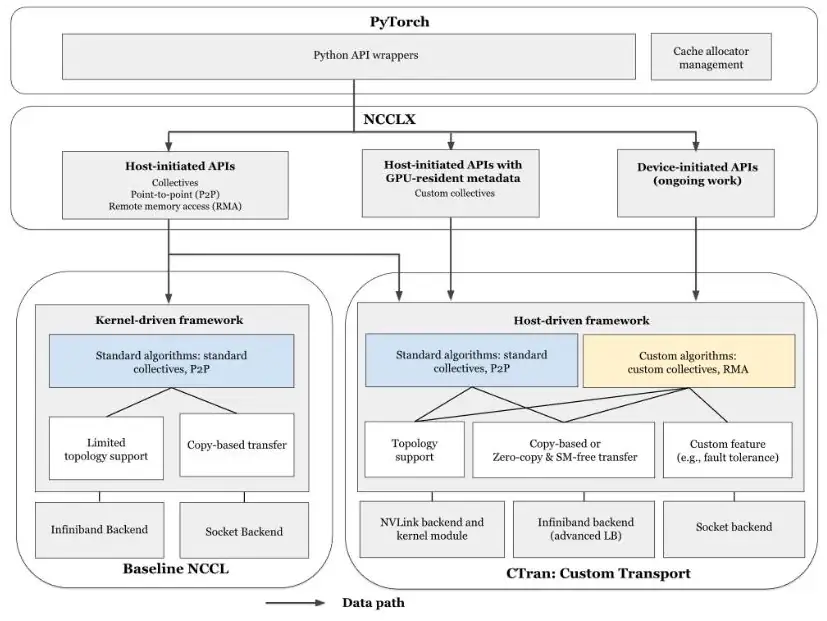
NCCLX sits under PyTorch and sends each call either to baseline NCCL or to CTran, its own transport with NVLink, IB/RoCE and socket back ends. Environment variables choose the path for classic calls; operations that NCCL lacks, such as one-sided remote writes (RMA), always use CTran. The paper's Figure 2 (below) draws the stack.
NCCLX 位於 PyTorch 之下,把每次呼叫交給原本的 NCCL,或交給它自己的傳輸層 CTran;CTran 有 NVLink、IB/RoCE 與 socket 三種後端。傳統呼叫以環境變數選擇路徑;NCCL 沒有的操作,例如單邊遠端寫入(RMA),一律走 CTran。論文的 Figure 2(下圖)畫出這個堆疊。
3.1 CTran: host-driven and zero-copy3.1 CTran:由主機驅動、零複製
Host-driven. One CPU thread per communicator issues the network operations. A small "stall kernel" keeps the order of the CUDA stream and synchronizes with the thread through a flag in host-pinned memory, in under 1 µs. In a network-only collective, such as a PP transfer, the GPU does no data work.
由主機驅動。每個 communicator 用一條 CPU 執行緒發出網路操作。一個小型「stall kernel」維持 CUDA stream 的順序,並透過 host-pinned 記憶體中的旗標與這條執行緒同步,耗時不到 1 µs。在只用網路的集體操作中,例如 PP 傳輸,GPU 完全不處理資料。
Zero-copy. The NIC writes directly from the sender's user buffer into the receiver's user buffer, after one control message carries the receiver's buffer address and key (Diagram B). The NIC can use only registered memory. Registration costs hundreds of µs to a few ms per medium buffer, with spikes to about 100 ms, so NCCLX registers PyTorch's cached memory segments lazily or uses a pre-registered memory pool. A PP send becomes one RDMA write with no SMs.
零複製。一則控制訊息帶來收端的緩衝區位址與 key 之後,NIC 就直接從送端的使用者緩衝區寫進收端的使用者緩衝區(示意圖 B)。NIC 只能使用已註冊的記憶體。中型緩衝區的註冊要花數百 µs 到數 ms,偶爾暴增到約 100 ms,所以 NCCLX 延後註冊 PyTorch 快取的記憶體區段,或使用預先註冊的記憶體池。一次 PP send 變成一次不用 SM 的 RDMA 寫入。
3.2 DQPLB: a cap on bytes in flight, per distance class3.2 DQPLB:依距離類別設定的在途位元組上限
NCCL's staging slots also let the receiver pace the sender. Zero-copy removes them, and the paper reports that zero-copy alone "resulted in suboptimal performance". Dynamic Queue Pair Load Balancing (DQPLB) puts a bound back (Diagram C). Each connection has one control QP and several data QPs. A message is cut into segments that go round-robin over the data QPs, and each data QP may have only a few unacknowledged writes; a full QP waits for a completion event (CQE). QPs on congested paths complete slowly, so the faster QPs carry more of the message. Segments can arrive out of order, so each RDMA_WRITE_WITH_IMM carries a sequence number in its 32-bit immediate value, and the receiver reorders the segments in a hash map with a sliding window. Small messages skip this and use one dedicated data QP.
NCCL 的暫存槽也讓收端控制送端的節奏。零複製拿掉了它們,論文指出單靠零複製「效能並不理想」。Dynamic Queue Pair Load Balancing(DQPLB)把上限加了回來(示意圖 C)。每條連線有一個控制 QP 與數個資料 QP。訊息被切成分段,輪流交給各資料 QP,每個資料 QP 只能有少數未確認的寫入;滿了的 QP 要等完成事件(CQE)。壅塞路徑上的 QP 完成得慢,所以較快的 QP 承載訊息的較大部分。分段可能亂序到達,所以每個 RDMA_WRITE_WITH_IMM 都在 32 位元 immediate 值中帶著序號,收端用雜湊表與滑動視窗重新排序。小訊息跳過這一切,只走一個專用的資料 QP。
The number of data QPs, the cap per QP and the largest segment are set per connection class; far peers get more QPs and more outstanding writes. In the terms of Section 4.6, the cap of class should cover that class's BDP:
資料 QP 的數量、每個 QP 的上限與最大分段都依連線類別設定;遠的對等端有更多 QP 與更多未確認寫入。用第 4.6 節的語言來說,類別 的上限 應涵蓋該類別的 BDP:
The paper does not publish the values. Together with load-balancing changes and tuned virtual output queues (VOQs) in the spine switches, DQPLB cut switch buffer build-up by an order of magnitude compared with Llama 3 training. The panel shows why one cap cannot serve all four classes.
論文沒有公布實際數值。DQPLB 加上負載平衡的改動與 spine 交換器虛擬輸出佇列(VOQ)的調校,使交換器緩衝區的堆積比 Llama 3 訓練時少了一個數量級。下面的面板說明,為何一個上限無法同時照顧四種類別。
3.3 Features for training and inference3.3 為訓練與推論加入的功能
FTAR. Meta trains with hybrid sharding (HSDP): FSDP inside replica groups of 4K GPUs, data parallelism across them. A failure shuts down only its group, which rejoins after repair. The AllReduce across groups is FTAR, a fault-tolerant ring AllReduce whose fixed chunk size and chunk count bound the bytes outstanding between neighbors. Chunks of 8 MB saturate the network with 2 thread blocks of 512 threads; NCCL's default is 4 blocks of 544.
FTAR。Meta 以混合分片(HSDP)訓練:4K GPU 的 replica group 內用 FSDP,group 之間用資料平行。故障只會關閉它所在的 group,修好後再加回來。group 之間的 AllReduce 是 FTAR,一種容錯的環形 AllReduce,固定的 chunk 大小與數量限制了鄰居之間的未完成位元組。8 MB 的 chunk 用 2 個 512 執行緒的 thread block 就能讓網路飽和;NCCL 預設是 4 個 544 執行緒的 block。
AllToAllvDynamic. Under CUDA graphs, NCCL's AllToAllv freezes its per-peer counts at capture, so MoE inference must pad every count to the worst case, all tokens to one expert. AllToAllvDynamic reads the counts from GPU memory when it runs and sends only real tokens.
AllToAllvDynamic。在 CUDA graph 下,NCCL 的 AllToAllv 在擷取時就固定每個對等端的計數,所以 MoE 推論必須把每個計數補到最壞情況,也就是所有 token 都送往同一個專家。AllToAllvDynamic 在執行時才從 GPU 記憶體讀取計數,只送真正的 token。
3.4 The control plane at 100K ranks3.4 10 萬個 rank 的控制平面
Startup. Stock NCCL discovered peers serially: the last of 100K ranks waited about 100 s for the bootstrap server. TCP listen queues overflowed beyond 64K ranks, rings formed through rank 0 one rank at a time, and an topology computation took about 10 s at 48K ranks. NCCLX splits sub-groups from one global communicator, bootstraps through a TCPStore, uses a bidirectional AllGather ( steps, not ), makes the CPU algorithms and connects peers on first use.
啟動。原版 NCCL 循序地發現對等端:10 萬個 rank 中最後一個要等約 100 s 才連上 bootstrap 伺服器。超過 64K 個 rank 時 TCP listen 佇列會溢位,環要經由 rank 0 一個一個組成,而 的拓樸計算在 48K 個 rank 時要約 10 s。NCCLX 從一個全域 communicator 切出子群組、透過 TCPStore 做 bootstrap、使用雙向 AllGather( 步而非 步)、讓 CPU 演算法變成 ,並在第一次使用時才連接對等端。
Memory and tools. Lazy connections, lazy channels and a slab allocator defer or pack allocations. CollTrace records every collective and RDMA operation; its analyzer traced the repeated restarts of an 8K-GPU job to one NIC. A CPU emulator ran 96K-rank tests on 3,072 CPU servers.
記憶體與工具。延後連線、延後配置 channel 與 slab 配置器把配置延後或打包。CollTrace 記錄每次集體操作與 RDMA 操作;它的分析器把一個 8K GPU 任務的反覆重啟追到一張 NIC。CPU 模擬器以 3,072 台 CPU 伺服器做了 96K 個 rank 的測試。
4. Implementation4. 實作
NCCLX is a fork of NCCL: baseline NCCL stays inside it, and CTran is added as a new transport path. It plugs into PyTorch's process-group backend. The paper gives no line count and no base version; it notes that NVIDIA shipped similar memory features from NCCL v2.22. NCCLX runs Llama 4 training and inference at Meta.
NCCLX 是 NCCL 的分支:原本的 NCCL 留在裡面,CTran 作為新的傳輸路徑加入。它接上 PyTorch 的 process-group 後端。論文沒有給程式碼行數與基底版本;它提到 NVIDIA 從 NCCL v2.22 起推出了類似的記憶體功能。NCCLX 在 Meta 用於 Llama 4 的訓練與推論。
5. What was measured5. 量到了什麼
All numbers come from Meta's production fabric and hosts, not from simulation. The paper names H100 GPUs and ConnectX-7 NICs in places, but many microbenchmarks state neither the GPU count nor the hardware.
所有數字都來自 Meta 的生產網路與主機,不是模擬。論文在部分地方提到 H100 GPU 與 ConnectX-7 NIC,但許多微基準測試既沒說 GPU 數量,也沒說硬體。
| Test測試 | Setup設定 | Measured實測結果 |
|---|---|---|
| Training訓練 | Llama 4, "various scales"Llama 4,「各種規模」 | Step latency up to 12% lower than with NCCL每步延遲比 NCCL 最多低 12% |
| Startup啟動 | 96K GPUs; 16K GPUs96K 顆 GPU;16K 顆 GPU | Up to 11× faster (baseline over 4 min); topology formation 18.45 → 4.1 s at 16K最多快 11 倍(基準超過 4 分鐘);16K 時拓樸建立 18.45 → 4.1 s |
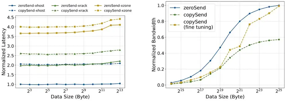
| Copy vs zero-copy複製對零複製 | Two GPUs across hosts, racks, zones兩顆 GPU,跨主機、機櫃、zone | Copying adds a fixed cost per transfer, up to 2× the time across hosts複製為每次傳輸增加固定成本,跨主機時最多 2 倍時間 |
| PP send/receivePP send/receive | 1–128 MB1–128 MB | Zero-copy 1.09–2.7× faster零複製快 1.09–2.7 倍 |
| TP overlapTP 重疊 | One node; 32 MB × 7 per rank單一節點;每 rank 32 MB × 7 | 1.57× lower latency than without overlap延遲比不重疊低 1.57 倍 |
| FTAR | AllReduce; scale not statedAllReduce;未說明規模 | About equal to NCCL with 2 vs 4 blocks; 9–18% faster at 2 blocks each以 2 對 4 個 block 與 NCCL 大致相當;兩者都 2 個 block 時快 9–18% |
| Small AllToAll小型 AllToAll | H100 nodes; setup stated two ways (section 6)H100 節點;設定有兩種說法(第 6 節) | 50% control messages, 20% posting, 30% waiting50% 控制訊息、20% 發出、30% 等待 |
The paper's Figure 7 (below) is the copy-versus-zero-copy row of the table. Read off its left plot, copying doubles small-message latency between hosts (2.0 against 1.0, normalized) and adds about 10% across zones (4.0 against 3.65). On the right, copy-based transfer without tuning reaches only about 0.57 of the bandwidth at 32 MB.
論文的 Figure 7(下圖)就是上表「複製對零複製」那一列。從左圖讀,跨主機時複製讓小訊息延遲變成兩倍(正規化後 2.0 對 1.0);跨 zone 時只多約 10%(4.0 對 3.65)。右圖中,未調校的複製式傳輸在 32 MB 時只達到約 0.57 的頻寬。
Memory. Table 4 of the paper measures each feature on its own in Llama 4 pre-training on 64K GPUs (HBM per GPU). The rows do not chain, and overall NCCL's footprint fell by almost half:
記憶體。論文的 Table 4 在 64K 顆 GPU 的 Llama 4 預訓練中分別量測每項功能(每顆 GPU 的 HBM)。這些列不能串起來看,整體而言 NCCL 的用量減少了將近一半:
| Feature功能 | Before → after之前 → 之後 | Saved節省 |
|---|---|---|
| Lazy algorithm connect演算法延後連線 | 8.09 → 6.65 GB | 1.44 GB |
| CTran lazy connectCTran 延後連線 | 6.65 → 5.86 GB | 0.79 GB |
| Slab allocatorslab 配置器 | 5.09 → 4.70 GB | 0.39 GB |
| Lazy channel allocationchannel 延後配置 | 5.39 → 4.20 GB | 1.19 GB |
MoE decode. Diagram D plots two rows of Table 3: Llama 4 Maverick decode with each token routed to its top experts, on 4, 8 and 16 hosts. The padded baseline grows with the number of hosts; AllToAllvDynamic stays nearly flat.
MoE 解碼。示意圖 D 畫出 Table 3 的兩列:每個 token 路由到前 個專家的 Llama 4 Maverick 解碼,在 4、8 與 16 台主機上。補齊計數的基準隨主機數增加;AllToAllvDynamic 幾乎持平。
Derived from the paper's numbers:
由論文數字推導:
| Question問題 | Calculation算式 | Result結果 |
|---|---|---|
| NCCL's share of an 80 GB H100's HBMNCCL 占一顆 80 GB H100 HBM 的比例 | ||
| Decode, , batch 256, 16 hosts: 164.29 → 27.43 ms解碼,、batch 256、16 台主機:164.29 → 27.43 ms | lower latency延遲降低 | |
| Topology computation at 100K ranks, if purely from 10 s at 48K若拓樸計算純粹是 ,由 48K 時的 10 s 推到 100K | sthe paper projects about 100 s論文預估約 100 s | |
| A cap that fills a same-rack path, used toward another zone (15×)填滿同一機櫃路徑的上限,用在其他 zone(15 倍) | link utilization鏈路使用率 |
Table 3's best case, about 83%, is slightly above the stated 15–80%, and the startup projection must include more than the quadratic term.
Table 3 最好的情況約 83%,略高於論文所說的 15–80%;啟動預估也必定不只包含二次項。
6. Limits and open questions6. 限制與未解的問題
The paper's own limits: zero-copy without DQPLB underperformed; NCCL's own zero-copy was unusable in production because PyTorch's expandable segments force re-registration; registration spikes are unresolved; and global NCCL settings that help a benchmark can hurt other collectives, such as the MoE AllToAll. A careful reader adds:
論文自己的限制:沒有 DQPLB 的零複製表現不佳;NCCL 自己的零複製在生產環境無法使用,因為 PyTorch 的 expandable segments 迫使重新註冊;註冊暴增尚未解決;而對基準測試有幫助的全域 NCCL 設定,可能傷害其他集體操作,例如 MoE AllToAll。細心的讀者還應補上:
- Evidence. The headline numbers (12%, 11×, an order of magnitude less buffering) come without a figure, scale or baseline configuration, and the small-AllToAll profile states two different setups (8 MB on 128 GPUs in the text, under 128 KB per rank on 32 × 8 in the caption). The design clearly works at Meta; the size of its gains elsewhere is uncertain.證據。主要數字(12%、11 倍、緩衝堆積少一個數量級)都沒有附圖、規模或基準設定,小型 AllToAll 的剖析還寫了兩種設定(正文是 128 顆 GPU、8 MB,圖說是 32 × 8、每 rank 小於 128 KB)。此設計在 Meta 顯然可行;在其他地方能增益多少則不確定。
- DQPLB is a static cap, not congestion control. It does not react to other jobs, its values are unpublished, and the paper does not discuss how the extra data QPs interact with ECMP or PFC.DQPLB 是靜態上限,不是壅塞控制。它不會對其他任務做出反應,數值沒有公布,論文也沒討論額外的資料 QP 與 ECMP 或 PFC 如何互動。
- Coarse fault handling. A failure removes a whole 4K-GPU replica group; the PReCCL digest shows the other extreme, one channel of one collective.粗粒度的故障處理。一次故障會移除整個 4K GPU 的 replica group;PReCCL 導讀展示另一個極端:一次集體操作中的一個 channel。
- Version. We read the open arXiv preprint, whose title ("Collective Communication for 100k+ GPUs") and author list differ from the SIGCOMM paper; changes in the final text are unknown.版本。我們讀的是公開的 arXiv 預印本,其標題("Collective Communication for 100k+ GPUs")與作者名單和 SIGCOMM 論文不同;正式版本是否有改動並不清楚。
7. How it connects7. 與其他內容的關聯
- Deep dive: Diagram B is section 5's copy path with the copies removed; DQPLB is section 6's bound, set once per distance class; transfers without copy kernels leave the SMs to section 7's overlap; sections 9.3–9.4 summarize CTran and AllToAllvDynamic.第 4 章:示意圖 B 是第 5 節的複製路徑拿掉複製後的樣子;DQPLB 是第 6 節的上限,按距離類別各設一次;沒有複製 kernel 的傳輸把 SM 留給第 7 節的重疊;第 9.3–9.4 節摘要了 CTran 與 AllToAllvDynamic。
- Guided readings: Meta RoCE paced senders with the CTS in one AI zone; NCCLX keeps that idea as per-QP caps across buildings. IRN capped each QP at one BDP inside the NIC; DQPLB does it in software, per class. The transport and failures chapters cover these caps and recovery loops.論文導讀:Meta RoCE 在一個 AI zone 內以 CTS 控制送端節奏;NCCLX 把這個想法保留為跨建築的每 QP 上限。IRN 在 NIC 內把每個 QP 限制在一個 BDP;DQPLB 在軟體中按類別做同樣的事。傳輸與故障第 4 章涵蓋這些上限與復原循環。
- Research digests: Theseus also separates the algorithm from the transport and adds run-time schedule swaps; PReCCL re-weights NCCL's channels from in-library telemetry instead of a static cap.研究導讀:Theseus 同樣把演算法與傳輸層分開,並加入執行期的排程抽換;PReCCL 依函式庫內的遙測重新分配 NCCL 各 channel 的權重,而不是用靜態上限。
Key numbers關鍵數字
| Number | 數字 | Meaning (Meta production unless noted) | 意義(除非另註,皆為 Meta 生產環境) |
|---|---|---|---|
| 7× · 15× · 30× | Latency vs same rack: cross-rack, cross-zone, cross-building | 相對同一機櫃的延遲:跨機櫃、跨 zone、跨建築 | |
| Lower Llama 4 training step latency | Llama 4 訓練每步延遲的降幅 | ||
| Faster process-group creation at 96K GPUs (baseline over 4 min) | 96K GPU 時 process group 建立的加速(基準超過 4 分鐘) | ||
| ≈ 10 GB → ≈ ½ | NCCL's HBM per H100 across 10+ communicators, and after NCCLX | NCCL 在 10 個以上 communicator 中占每顆 H100 的 HBM,以及用 NCCLX 之後 | |
| 1.09–2.7× | Zero-copy vs copy-based PP send/receive, 1–128 MB | 零複製對複製式 PP send/receive,1–128 MB | |
| 9–18% | FTAR vs NCCL, both with 2 thread blocks | FTAR 對 NCCL,兩者都用 2 個 thread block | |
| 15–80% | Lower Llama 4 Maverick decode latency, 4–16 hosts | Llama 4 Maverick 解碼延遲降幅,4–16 台主機 | |
| Less switch buffer build-up than in Llama 3, "an order of magnitude" (with load-balancing and VOQ changes) | 交換器緩衝區堆積比 Llama 3 少「一個數量級」(含負載平衡與 VOQ 改動) |
Terms used on this page本頁用到的術語
- CTran
- NCCLX's own host-driven transport, with NVLink, IB/RoCE and socket back ends.
- NCCLX 自己的主機驅動傳輸層,有 NVLink、IB/RoCE 與 socket 後端。
- Zero-copy
- The NIC or copy engine moves data between registered user buffers, with no staging copies.
- 由 NIC 或複製引擎在已註冊的使用者緩衝區之間搬資料,不經暫存複製。
- DQPLB
- Dynamic Queue Pair Load Balancing: segments sprayed over several data QPs, with a cap on outstanding writes per QP set per distance class.
- Dynamic Queue Pair Load Balancing:把分段噴灑到多個資料 QP,每個 QP 的未確認寫入上限依距離類別設定。
- Connection class連線類別
- Same rack, cross-rack in a zone, cross-zone in a building, or cross-building.
- 同一機櫃、同 zone 跨機櫃、同建築跨 zone,或跨建築。
- FTAR
- Fault-tolerant ring AllReduce across HSDP replica groups, with a fixed chunk size and count.
- 跨 HSDP replica group 的容錯環形 AllReduce,chunk 大小與數量固定。
- AllToAllvDynamic
- An AllToAllv that reads its per-peer counts from GPU memory when it runs.
- 在執行時才從 GPU 記憶體讀取各對等端計數的 AllToAllv。