PSN-PATH: When Multipath RDMA Meets Lossy NetworksPSN-PATH:當多路徑 RDMA 遇上有損網路
After reading, you can explain why a NIC that sprays one queue pair over several paths mistakes late packets for lost ones, and how PSN-PATH's lanes tell the two apart.讀完後,你能說明把一個 queue pair 噴灑到多條路徑的 NIC 為何把晚到的封包誤當遺失,以及 PSN-PATH 的「通道」如何分辨兩者。
Two trends meet inside the NIC: spraying one queue pair over several paths, and lossy RDMA without PFC. Go-back-N and IRN-style selective retransmission both treat a gap in the packet sequence number (PSN) as a loss, but on several paths a packet that is only late makes the same gap. PSN-PATH splits each queue pair into lanes, lane , and pins each lane to one UDP source port, so plain ECMP keeps each lane on one first-in, first-out path. A gap inside a lane is then a real loss, and a gap across lanes is only reordering: when PSN arrives, the receiver checks whether arrived. A boundary field marks where a lane moved, and a score of ACKs minus half the NACKs moves lanes off lossy paths. Nothing ran on real switches or NICs. FPGA synthesis estimates 55.3% fewer LUTs and 83.7% less block RAM than MP-RDMA; the throughput and completion-time results come from FPGA-emulated switches and simulation and are not shown here.
兩個趨勢在 NIC 裡相遇:把一個 queue pair 噴灑到多條路徑,以及不用 PFC 的有損 RDMA。Go-back-N 與 IRN 式選擇性重傳都把封包序號(PSN)的缺口當成遺失,但路徑一多,只是晚到的封包也會造成同樣的缺口。PSN-PATH 把每個 queue pair 分成 條通道(lane),通道 ,並把每條通道固定在一個 UDP 來源埠上,於是一般的 ECMP 讓每條通道都走一條先進先出的路徑。通道內的缺口就是真正的遺失,跨通道的缺口只是亂序:PSN 到達時,接收端檢查 是否已到。一個邊界欄位標出通道換路徑的位置,「ACK 減一半 NACK」的分數則把通道移離有丟包的路徑。整篇論文沒有在真實的交換器或 NIC 上執行。FPGA 合成估計它比 MP-RDMA 少用 55.3% 的 LUT 與 83.7% 的 block RAM;吞吐量與完成時間的結果來自 FPGA 模擬的交換器與模擬器,本頁不列出。
1. Where this paper sits1. 這篇論文的位置
Section 8.5 ends with packet spraying, whose price is out-of-order arrival; the IRN guided reading shows that selective retransmission pays it cheaply (loss recovery is §2 of Chapter 7). One question stays open: when does a gap mean loss? IRN's receiver treats every gap as a loss. On one path that is correct, because a later packet overtakes an earlier one only if the earlier one was dropped. On several paths it is wrong. Earlier multipath NICs wait instead: MP-RDMA resends when its out-of-order bitmap overflows, ORNIC when a gap exceeds a tolerance distance, and both delay every real loss. Falcon infers loss from time; DCP has switches trim packets. PSN-PATH infers loss from structure, with the knob of §6 of Chapter 8, the UDP source port, used inside one queue pair.
第 8.5 節以封包噴灑作結,它的代價是亂序到達;IRN 導讀說明選擇性重傳能便宜地付出這個代價(丟包恢復見第 7 章 第 2 節)。還留下一個問題:缺口何時代表遺失?IRN 的接收端把每個缺口都當成遺失。在一條路徑上這是對的,因為較晚的封包只有在較早的封包被丟掉時才可能超越它。在多條路徑上就錯了。早期的多路徑 NIC 改用等待:MP-RDMA 等亂序位圖溢出才重送,ORNIC 等缺口超過容忍距離,兩者都拖慢每一次真正的遺失。Falcon 從時間推斷遺失;DCP 讓交換器裁切封包。PSN-PATH 從結構推斷遺失,並把第 8.6 節的旋鈕——UDP 來源埠——用在一個 queue pair 內部。
2. The problem: late or lost?2. 問題:晚到還是遺失?
Packets that share a switch queue leave it in the order they entered. So packets on one physical path stay in order, and only packets on different paths overtake each other. Figure 1 shows what this means at the receiver. In case A one lane is slow and nothing is lost: a receiver that treats any gap as a loss sends three NACKs, and all three are false. In case B packet 6 is dropped: both rules find it, but the per-lane rule waits for the next packet of the same lane, four packets later.
共用一個交換器佇列的封包,以進入的順序離開。所以同一條實體路徑上的封包保持順序,只有不同路徑上的封包會互相超越。圖 1 說明這對接收端的意義。情況 A 中有一條通道較慢、沒有任何遺失:把任何缺口都當遺失的接收端送出三個 NACK,三個都是誤判。情況 B 中封包 6 被丟掉:兩種規則都找得到它,但通道規則要等同一通道的下一個封包,也就是四個封包之後。
The paper's motivating runs use its emulated network (§5): there, multipath IRN retransmitted far more than single-path IRN even with no injected loss. This page gives no numbers from them, because the network was a model.
論文說明動機的執行用的是它的模擬網路(第 5 節):在那裡,即使沒有注入丟包,多路徑 IRN 的重傳也遠多於單路徑 IRN。本頁不引用那些數字,因為那個網路是模型。
A fix per path is expensive: an expected PSN, a bitmap and a timer for every path. For 10K queue pairs and 64 paths the paper estimates about 80 MB of state, more than the 64 MB of SRAM it assumes for a ConnectX-7/8-class NIC (§3.1, analysis). PSN-PATH keeps one bitmap per queue pair.
逐路徑的修法很昂貴:每條路徑都要一個預期 PSN、一張位圖與一個計時器。對 10K 個 queue pair、64 條路徑,論文估計約需 80 MB 狀態,超過它為 ConnectX-7/8 等級 NIC 假設的 64 MB SRAM(§3.1,分析)。PSN-PATH 每個 queue pair 只保留一張位圖。
3. The design3. 設計
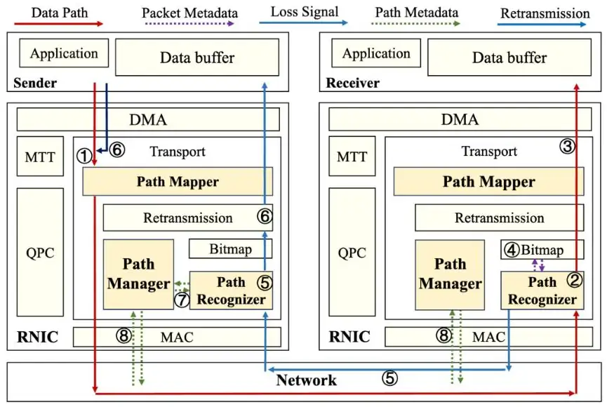
Three blocks in the RNIC data plane do the work: the Path Mapper at the sender, the Path Recognizer at the receiver, and the Path Manager at both ends. No switch changes.
RNIC 資料平面中的三個區塊負責這些工作:發送端的 Path Mapper、接收端的 Path Recognizer,以及兩端都有的 Path Manager。交換器不需修改。
3.1 Lanes pinned to source ports3.1 固定在來源埠上的通道
The Mapper puts each packet on a logical path, a lane, and turns the lane into a UDP source port:
Mapper 把每個封包放到一條邏輯路徑(通道)上,再把通道換算成 UDP 來源埠:
Lane carries PSNs , and is a per-lane offset. Switches hash the five-tuple as usual, so a lane takes one path and FIFO queues keep it in order; to move a lane, the sender changes . The default is . A 7-byte Path ID after the base transport header carries , and the lane boundary (2 + 2 + 3 bytes). Figure 2 shows the assumption behind this: one source port must map to one path.
通道 承載 PSN , 是每條通道的偏移量。交換器照常對五元組做雜湊,所以一條通道走一條路徑,FIFO 佇列讓它保持順序;要搬移通道,發送端只要改 。預設 。基本傳輸標頭之後的 7 位元組 Path ID 帶著 、 與通道邊界 (2 + 2 + 3 位元組)。圖 2 畫出這背後的假設:一個來源埠必須對應一條路徑。
3.2 The stateless check3.2 無狀態檢查
When PSN arrives, the Recognizer marks it in the queue pair's bitmap and looks up the same-lane predecessor . If is marked, is out of order only across lanes and is accepted. If not, was lost, because both packets used one FIFO path, and the receiver sends a NACK at once: no timer, no wait for the bitmap to fill. The sender counts the failure against that path and resends the packet. The copy keeps its PSN and , so it may take a healthier path if the lane has moved, and the bitmap drops duplicates. The paper calls this a stateless backtracking check: no per-path expected PSN, bitmap or timer, only a 32-bit bitmap per queue pair in the prototype.
PSN 到達時,Recognizer 在該 queue pair 的位圖上標記它,再查同一通道的前一個封包 。若 已標記, 只是跨通道亂序,接收端接受它。若沒有, 就遺失了,因為兩個封包走同一條 FIFO 路徑,接收端立刻送出 NACK:不用計時器,也不等位圖填滿。發送端把這次失敗記在那條路徑上,並重送該封包。副本保留原來的 PSN 與 ,所以若通道已經搬家,它可以走較健康的路徑,重複的封包由位圖丟棄。論文稱之為無狀態回溯檢查:沒有逐路徑的預期 PSN、位圖或計時器,原型中每個 queue pair 只有一張 32 位元的位圖。
The panel replays one trace through three receivers. Go-back-N and plain selective repeat both use the global rule; the per-lane check is PSN-PATH's.
下面的面板讓同一段紀錄通過三種接收端。Go-back-N 與一般的選擇性重傳都用全域規則;通道檢查是 PSN-PATH 的規則。
Set : all three receivers agree, because one lane is one path. At , raise the skew to 500 µs: why does selective repeat climb while the per-lane check stays at zero? Then switch to spraying. What does the per-lane count now say about the switches PSN-PATH needs?
把 設為 1:三種接收端結果一致,因為一條通道就是一條路徑。回到 ,把偏差調到 500 µs:為何選擇性重傳的數字上升,通道檢查卻維持零?再切到噴灑。通道檢查的數字現在說明 PSN-PATH 需要什麼樣的交換器?
3.3 Moving a lane without false alarms3.3 搬移通道而不誤報
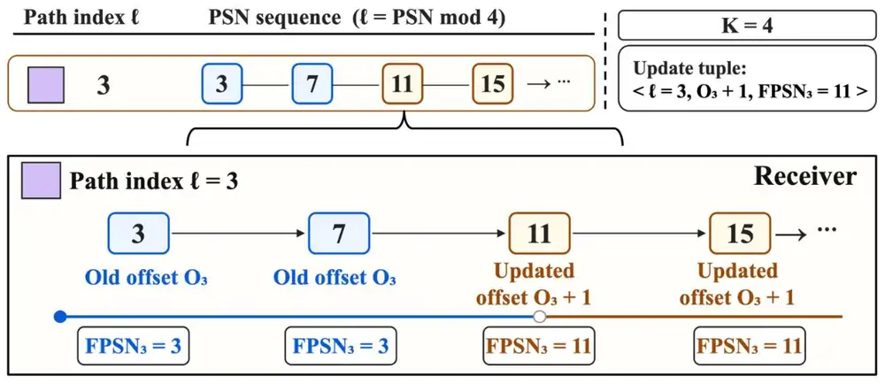
Moving a lane creates a new risk: old-path packets may still be in flight when the first new-path packet arrives, and a faster new path shows before . So every packet carries , the PSN of the first packet on the lane's current path, and the receiver keeps its own copy . Four cases follow (§3.3.2):
搬移通道帶來新的風險:新路徑的第一個封包到達時,舊路徑的封包可能還在路上,而較快的新路徑會讓 比 先到。所以每個封包都帶著 ,即該通道目前路徑上的第一個封包的 PSN,接收端則保留自己的副本 。由此分出四種情況(§3.3.2):
- First packet on a new path (, ): adopt the new boundary; skip the check.新路徑上的第一個封包(、):採用新邊界;略過檢查。
- Normal packet (): check .一般封包():檢查 。
- Old-path packet after the move (): accept; check as usual.搬移後才到的舊路徑封包():接受;照常檢查 。
- Last old-path packet lost (): nothing later on that path can reveal it, so a timeout of unstated length recovers it.舊路徑上最後一個封包遺失():那條路徑上沒有更晚的封包能揭露它,所以靠一個長度未說明的逾時恢復。
3.4 Scoring paths, and moving slowly3.4 為路徑評分,並慢慢搬移
The Manager scores each lane once per epoch of one RTT:
Manager 每個 RTT 為每條通道評分一次:
ACK counts packets delivered without retransmission, NACK confirmed losses. Two thresholds drive DT-Switch (double-threshold switching). Below the path is removed: the sender raises until it finds a healthy path and sets a new . Between and the Manager scores a candidate offset and, if it does at least as well, moves traffic gradually (Figure 5). The thresholds fit only a score normalized per packet, which the paper's code defines as .
ACK 計算不需重傳就送達的封包,NACK 計算確認的遺失。兩個門檻驅動 DT-Switch(雙門檻切換)。低於 時移除該路徑:發送端遞增 直到找到健康的路徑,並設定新的 。介於 與 之間時,Manager 為一個候選偏移量評分,若它不比原路徑差,就逐步移轉流量(圖 5)。這些門檻只適用於逐封包正規化的分數,論文的程式碼把它定義為 。
4. Implementation4. 實作
The prototype is C++ for Xilinx Vitis HLS, targeting an Alveo U50 FPGA on a RoCEv2 base. The Mapper sits between the transport header and UDP/IP encapsulation and takes one packet per clock; the Recognizer keeps the bitmap in block RAM (BRAM) and finishes a check in one cycle; the Manager is an event-driven state machine. The paper gives no clock frequency, no lines of code and no throughput measured on a board. Its cost numbers are synthesis estimates (Tables 1–2), not measurements of a running design:
原型以 C++ 撰寫給 Xilinx Vitis HLS,目標是 Alveo U50 FPGA,基於 RoCEv2。Mapper 位於傳輸標頭與 UDP/IP 封裝之間,每個時脈處理一個封包;Recognizer 把位圖放在 block RAM(BRAM)中,一個週期完成一次檢查;Manager 是事件驅動的狀態機。論文沒有給時脈頻率、程式碼行數,也沒有在板子上量測的吞吐量。它的成本數字是合成估計(Tables 1–2),不是運行中設計的量測:
| Design (synthesis estimate)設計(合成估計) | LUTs | FFs | BRAM (36 Kb blocks)BRAM(36 Kb 區塊) |
|---|---|---|---|
| MP-RDMA (baseline)MP-RDMA(基準) | 18,240 | 26,450 | 86 |
| PSN-PATH, , totalPSN-PATH,,總計 | 8,142 | 12,725 | 14 |
| · Path Mapper / Recognizer / Manager· Path Mapper / Recognizer / Manager | 1,245 / 4,562 / 2,335 | 2,108 / 6,842 / 3,775 | 0 / 12 / 2 |
| PSN-PATH, / 16 / 32PSN-PATH, / 16 / 32 | 9,014 / 9,205 / 11,587 | 13,165 / 15,670 / 17,758 | 14 / 14 / 15 |
The paper states the saving as 55.3% of LUTs and 83.7% of BRAM, with about half the flip-flops: a per-QP bitmap and a lookup packets back replace MP-RDMA's deep out-of-order window. From to 32, LUTs grow about 42% and BRAM by one block.
論文把節省寫成 LUT 少 55.3%、BRAM 少 83.7%,正反器約減半:每個 QP 一張位圖加上往回 個封包的查詢,取代了 MP-RDMA 很深的亂序窗口。從 到 32,LUT 增加約 42%,BRAM 只多一個區塊。
5. What was evaluated5. 評估了什麼
Setup. The paper calls its first setup a real system testbed, but it has no commercial switch or NIC: subsystems on Alveo U50 FPGAs and a 15-switch leaf–spine written as a Vitis HLS switch model, forwarding at 100 Gb/s with emulated ECMP, injected queueing delays of 1–500 µs and injected loss of 0–1%. The second setup is ns-3: a 16 × 16 leaf–spine with 128–1,024 hosts, 100 Gb/s links and 0.4% default loss. The baselines are the authors' re-implementations of MP-CX5 (ConnectX-style go-back-N made multipath), MP-IRN, MP-RDMA, ORNIC and Falcon's loss logic. The workloads are WebSearch and one all-to-all in which each host sends a 10 MB flow to every other host in its group.
設定。論文把第一套設定稱為真實系統測試平台,但其中沒有商用交換器或 NIC:子系統跑在 Alveo U50 FPGA 上,15 台交換器的 leaf–spine 是 Vitis HLS 寫成的交換器模型,以 100 Gb/s 轉送、模擬 ECMP、注入 1–500 µs 的排隊延遲與 0–1% 的丟包。第二套設定是 ns-3:16 × 16 的 leaf–spine,128–1,024 台主機、100 Gb/s 鏈路、預設丟包 0.4%。基準是作者重新實作的 MP-CX5(改成多路徑的 ConnectX 式 go-back-N)、MP-IRN、MP-RDMA、ORNIC 與 Falcon 的丟包邏輯。工作負載是 WebSearch 與一種 all-to-all:每台主機對同組的每台其他主機送一條 10 MB 的流。
Results. All throughput, flow-completion and retransmission results come from FPGA-emulated switches or ns-3, so this page does not show them. Two choices rest on those runs, as claims rather than evidence: , from an ns-3 sweep in which larger added reordering and lane overhead, and the ablations' finding that fast retransmission and path switching both help. The only hardware numbers are the synthesis estimates above.
結果。所有吞吐量、流完成與重傳結果都來自 FPGA 模擬的交換器或 ns-3,所以本頁不列出。有兩項選擇建立在這些執行上,只能當主張而非證據: 來自一次 ns-3 掃描,其中較大的 帶來更多亂序與通道開銷;消融實驗則認為快速重傳與路徑切換都有幫助。唯一的硬體數字是上面的合成估計。
6. Limits and open questions6. 限制與未解的問題
The paper names three limits: a larger costs reordering and management, a lost last packet before a move waits for an unstated timeout, and and the thresholds need tuning. A careful reader adds six.
論文自己指出三個限制:較大的 帶來亂序與管理成本,搬移前最後一個封包若遺失要等一個未說明的逾時, 與門檻需要調整。細心的讀者還會補上六點。
- It needs switches that do not spray. The lane argument holds only while one source port maps to one path. Switch-side spraying or adaptive routing (SGLB's packet mode, InfiniBand adaptive routing, the random spraying that OmniPath Ping assumes) scatters a lane, and every reorder inside it becomes a false loss (Figure 2; the panel's spraying mode). An ECMP rehash after a link failure can also move a lane mid-flight. The paper discusses neither case: "no switch changes" means "switches must keep per-flow ECMP".它需要不做噴灑的交換器。通道論證只在一個來源埠對應一條路徑時成立。交換器端的噴灑或自適應路由(SGLB 的封包模式、InfiniBand 自適應路由、OmniPath Ping 所假設的隨機噴灑)會把通道撒開,通道內的每次亂序都變成誤判遺失(圖 2;面板的噴灑模式)。鏈路故障後的 ECMP 重新雜湊也可能把通道中途搬走。論文兩種情況都沒有討論:「不需修改交換器」其實是「交換器必須維持逐流 ECMP」。
- lanes are not paths. The ports hash independently: by chapter 06 §2, four ports on 16 uplinks share one about 33% of the time. DT-Switch reacts only to NACKs, never to queueing or ECN, so a lane on a congested but loss-free path stays there. 條通道不等於 條路徑。各埠獨立雜湊:依第 8 章 06 第 2 節,4 個埠落在 16 條上行時約有 33% 的機率共用一條。DT-Switch 只對 NACK 反應,從不理會排隊或 ECN,所以落在壅塞但不丟包路徑上的通道會一直留著。
- The bitmap window. A 32-bit bitmap faces an emulated delay spread of up to 500 µs, about 1,500 packets of 4 KB at 100 Gb/s. The paper does not say what happens when falls outside it.位圖窗口。32 位元的位圖要面對最多 500 µs 的模擬延遲差,在 100 Gb/s 下約是 1,500 個 4 KB 封包。論文沒有說明 落在窗口之外時會怎樣。
- The thresholds do not match their stated loss rates. The paper ties 0.95 and 0.85 to 0.4% and 1% loss, but a lane with loss rate scores (table below). As written, a lane at 1% loss is never even explored.門檻與它宣稱的丟包率對不上。論文把 0.95 與 0.85 對應到 0.4% 與 1% 的丟包,但丟包率 的通道得分是 (見下表)。照文中的設定,1% 丟包的通道連探索都不會觸發。
- Other slips. The "real system testbed" of §5.1 is what §7 calls trace-driven hardware simulation. §2.1 says go-back-N resends the packets before the lost PSN; it resends the lost packet and all after it. The claimed gains over ORNIC and Falcon exceed what Figure 9 plots. Figures 9 and 11 share a "one flow" label but not their goodput levels, FCT units change between figures, and §5.4.3 calls a falling trend "non-decreasing".其他疏漏。§5.1 的「真實系統測試平台」就是 §7 所說的 trace 驅動硬體模擬。§2.1 說 go-back-N 重送遺失 PSN「之前」的封包;實際上它重送遺失的封包及其後的全部封包。宣稱相對 ORNIC 與 Falcon 的增益超過 Figure 9 畫出來的。Figures 9 與 11 都標「一條流」,goodput 水準卻不同;FCT 的單位在各圖之間改變;§5.4.3 把下降的趨勢稱為「非遞減」。
- Baselines and the AI link. Falcon and ORNIC appear only as loss logic, the headline gains are against the go-back-N baseline, and DCP, Stellar-style many-path spraying and ConWeave are absent. The AI relevance is limited: one synthetic all-to-all benchmark and an SRAM example, with no collectives, GPUs, 400 Gb/s links or iteration times.基準與 AI 的關聯。Falcon 與 ORNIC 只以丟包邏輯出現,主要增益是相對 go-back-N 基準,也沒有 DCP、Stellar 式多路徑噴灑或 ConWeave 的比較。與 AI 的關聯有限:一個合成的 all-to-all 基準與一個 SRAM 例子,沒有集體通訊、GPU、400 Gb/s 鏈路或迭代時間。
| Question問題 | Calculation算式 | Result結果 |
|---|---|---|
| Normalized score of a lane with loss rate 丟包率 的通道正規化分數 | ||
| Score at the paper's 0.4% loss論文所說 0.4% 丟包時的分數 | above both thresholds高於兩個門檻 | |
| Score at the paper's 1% loss論文所說 1% 丟包時的分數 | still in the keep zone仍在保留區 | |
| Loss rate that reaches 達到 的丟包率 | ||
| Loss rate that reaches 達到 的丟包率 |
7. How it connects7. 與其他內容的關聯
- IRN and chapter 07 §2: accepting out-of-order packets is not the same as recognizing reordering.IRN 與第 8 章 07 第 2 節:接受亂序封包,不等於認得出亂序。
- Stellar makes the opposite bets in production: 128 paths, one shared congestion window and a 250 µs timeout, against four lanes and an immediate NACK backed only by simulation.Stellar 在生產環境下了相反的賭注:128 條路徑、一個共用的壅塞窗口、250 µs 逾時;PSN-PATH 則是四條通道與立即 NACK,只有模擬支持。
- SGLB decides per packet in the switch. PSN-PATH needs the switch not to, so the two combine only in SGLB's flow or flowlet mode.SGLB 在交換器裡逐封包決定路徑。PSN-PATH 需要交換器不這麼做,所以兩者只能在 SGLB 的逐流或 flowlet 模式下並用。
- OmniPath Ping monitors switch-sprayed fabrics; host-steered lanes like PSN-PATH's are the case it covers only in an appendix sketch.OmniPath Ping 監控由交換器噴灑的網路;像 PSN-PATH 這樣由主機控制路徑的通道,它只在附錄中略述。
- Meta RoCE and Alibaba HPN. Meta adds entropy with more queue pairs, PSN-PATH inside one. HPN's RePaC picks disjoint ports up front from the known hash; PSN-PATH searches offsets only after a path turns lossy.Meta RoCE 與 Alibaba HPN。Meta 用更多 queue pair 增加熵,PSN-PATH 在一個 queue pair 內增加。HPN 的 RePaC 依已知的雜湊事先挑出不相交的埠;PSN-PATH 只在路徑開始丟包後才搜尋偏移量。
Key numbers關鍵數字
| Number | 數字 | Meaning (kind of evidence) | 意義(證據種類) |
|---|---|---|---|
| 8,142 vs 18,240 | LUTs, PSN-PATH () vs MP-RDMA, −55.3% (Alveo U50 synthesis estimate) | LUT,PSN-PATH()對 MP-RDMA,−55.3%(Alveo U50 合成估計) | |
| 14 vs 86 | BRAM blocks, same comparison, −83.7% (synthesis estimate) | BRAM 區塊,同一比較,−83.7%(合成估計) | |
| 11,587 / 15 | LUTs / BRAM blocks at (synthesis estimate) | 時的 LUT / BRAM 區塊(合成估計) | |
| 80 MB > 64 MB | Per-path state for 10K QPs × 64 paths vs the assumed SRAM budget (paper's analysis) | 10K 個 QP × 64 條路徑的逐路徑狀態,對比假設的 SRAM 預算(論文的分析) | |
| 7 B | Path ID after the BTH: , , = 2 + 2 + 3 bytes (design) | BTH 之後的 Path ID:、、 = 2 + 2 + 3 位元組(設計) | |
| 4; 0.5; 0.95 / 0.85; 10 | Defaults: , , / , first (design) | 預設值:、、 / 、初始 (設計) | |
| 3.3% / 10% | Loss rates at which the normalized score hits 0.95 / 0.85 (our arithmetic) | 正規化分數落到 0.95 / 0.85 的丟包率(我們的計算) |
Terms used on this page本頁用到的術語
- Lane
- PSN-PATH's logical path , pinned to one UDP source port so that it stays on one path.
- PSN-PATH 的邏輯路徑 ,固定在一個 UDP 來源埠上,使它留在一條路徑上。
- ,
- The lane's port offset, and the PSN of the first packet on its current path, the boundary between old-path and new-path packets.
- 通道的埠偏移量,以及它目前路徑上第一個封包的 PSN,也就是舊路徑與新路徑封包的分界。
- Stateless backtracking check
- On arrival of PSN , test the per-QP bitmap for ; a miss means a real loss.
- PSN 到達時,在每個 QP 的位圖中檢查 ;缺席就代表真正的遺失。
- DT-Switch
- Double-threshold switching: explore a candidate path below , remove the path below , and shift traffic one packet in at a time.
- 雙門檻切換:低於 時探索候選路徑,低於 時移除路徑,並以每 個封包 1 個的方式移轉流量。
- Bitmap-overflow recovery / OTD
- The waiting rules of MP-RDMA (resend when the out-of-order window fills) and ORNIC (declare loss beyond a tolerance distance).
- MP-RDMA(亂序窗口填滿才重送)與 ORNIC(超過容忍距離才判定遺失)的等待式規則。
- Synthesis estimate
- The FPGA resources a compiler reports for a design; not a measurement of a running design.
- 編譯器為一個設計報告的 FPGA 資源用量;不是運行中設計的量測。